
neuromore Studio
Nodes
Nodes are the building blocks of a classifier. Each node does one job and passes its result on through its ports. You connect ports in the Classifier window to build a signal path, usually from sensors through signal processing to feedback. This page lists every node you can add in a standard production build, with its ports, attributes and default values.
Differences from the public release are marked. See What changed since 1.7.3.
The palette has one tab for each category, and each category has a section on this page: Sensors, Input, Output, Math, DSP, Bio and Utils.
Three nodes are hidden from the palette: Session Time and Body Feedback, which are deprecated, and Select Bins, which is flagged as unstable. To add one, right-click in the graph and use the Add Node menu.
State machines have their own objects: states, transitions, conditions and actions. See State machine reference.
These docs show what the neuromore system can do. Community builds on GitHub do not include every device driver. Developers can add those drivers in their own source build. Commercial clients can get the integration as part of their custom build. Each device is labelled, so check the label before you buy hardware.
A device node appears only if your build includes it and your account has access to it, so the palette can differ between builds, platforms and accounts. BrainFlow, Cyton and EEG Device are not limited by account, and neither are the nodes in the other categories. See Editions and licensing.
Ports of type Channels carry one or more channels of numeric samples. A set of channels on one port is called a multichannel. Ports of type Spectrum carry frequency spectra from an FFT node.
Some nodes need a fixed sample rate, or the same sample rate on all inputs. If an input doesn’t meet this, the node shows the error “Input must have a valid sample rate.” or “Input sample rates are incompatible.” and produces no output.
In 1.7.3: The node shows the same error but keeps running. The Operation node is the exception: it stops in both versions.
Session pause: no node has a pause attribute. During a pause the graph keeps updating, so sensor nodes keep delivering samples. Integral, Statistics, Auto Threshold, Points and Session Time freeze automatically, and the Paused output of Session Info is 1. See Running a session.
In 1.7.3: Integral, Statistics, Auto Threshold, Points and Session Time keep running during a pause. Only the Paused output of Session Info behaves the same.
Sensors Nodes
Section titled “Sensors Nodes”This category contains the nodes that bring device data into a classifier. Each device type has its own node, with one output port per data stream. The EEG Device node works with any EEG device. Sensor nodes have no input ports. See Biosensors for setup steps and Devices for transports and detection.
What all device nodes share:
- EEG devices: the EEG port bundles all electrodes into one multichannel output. If the device has more than one electrode, each electrode also gets its own port.
- Device not connected: the node shows this error when it finds no matching device that is streaming. It then carries no data.
- Battery low: the node can show this warning when a device reports less than 10% charge. It can also show for a device that reports no battery level, and then says nothing about a real battery.
Device nodes share the attributes below, except EEG Device, BrainFlow and Cyton, whose entries say so.
| Attribute | Values | Default | What it does |
|---|---|---|---|
| Upload | On, off | Off | Does not upload this node’s streams. Studio’s session upload reads this setting only on Output nodes, so use Upload on an Output node instead. Whether physiological data is uploaded also depends on your account. See Editions and licensing. |
| Device Number | 1 or higher | 1 | Picks which device of this type the node uses when several are connected. |
| Raw Output | On, off | Off | Outputs the device’s unsynced streams and bypasses drift correction. The device’s clock then drives the channels. |
EEG Device
Section titled “EEG Device”Reads EEG from any connected EEG device, so one classifier can work across different headsets. It outputs EEG only, with no per-electrode ports and no accelerometer or other extra streams.
| Port | Direction | Type | Meaning |
|---|---|---|---|
| EEG | Output | Channels | All electrodes of the device it found. When the node starts, the port takes the device’s name. |
| Attribute | Values | Default | What it does |
|---|---|---|---|
| Allowed Devices | List of device names or hexadecimal type IDs | Empty, which matches every EEG device | The node goes through the list in order and uses the first connected EEG device that matches. A name matches on any part of the hardware name, ignoring case, so muse matches InteraXon Muse. |
This node has no Upload, Device Number or Raw Output attribute. It always outputs synced channels.
With an empty list, the node also accepts the Test Device. When two or more EEG devices are connected, Studio shows an Active BCI selector. This node doesn’t read that selector, so use Allowed Devices to choose between devices.
Test System
Section titled “Test System”
Outputs simulated brainwaves from the Test Device, so you can build and run a classifier with no hardware. The signal mixes delta, theta, alpha and SMR sine waves with noise, at 128 Hz.
| Port | Direction | Type | Meaning |
|---|---|---|---|
| EEG | Output | Channels | All 8 simulated electrodes. |
| Pz, Cz, F3, F4, AF3, AF4, O1, O2 | Output | Channels | One simulated electrode per port. |
| Attribute | Values | Default | What it does |
|---|---|---|---|
| Upload, Device Number, Raw Output | See the shared table | Off, 1, Off | Shared device attributes. |
Availability: all platforms. Status: Beta.
Studio adds the Test Device when no other device exists, within about a second, and removes it when a real device connects. This needs Enable Test Devices (on by default) under NMStudio > Settings > Devices > Drivers, and your account must have access to the Test Device. So a classifier that uses this node loses its signal once a real device connects, and the node then shows Device not connected.
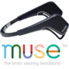
Reads an InteraXon Muse headband through the OSC stream from the external muse-io program. EEG runs at a nominal 220 Hz.
| Port | Direction | Type | Meaning |
|---|---|---|---|
| EEG | Output | Channels | All 4 electrodes. |
| TP9, Fp1, Fp2, TP10 | Output | Channels | One electrode per port. |
| Concentration, Mellow | Output | Channels | Experimental muse-io scores, 0 to 1, at 10 Hz. |
| DRL, Ref | Output | Channels | Driven right leg and reference, in µV, at 10 Hz. |
| Acc (Forward), Acc (Up), Acc (Left) | Output | Channels | Accelerometer axes in mm/s^2, at 50 Hz. |
| Eye Blink, Jaw Clench | Output | Channels | Blink and jaw clench detection from muse-io, 0 or 1, at 10 Hz. |
| TP9 OK?, Fp1 OK?, Fp2 OK?, TP10 OK? | Output | Channels | Contact quality per electrode: 1 good, 0.5 fair, 0 bad. |
| Put On? | Output | Channels | Whether the headband touches the forehead, 0 or 1. |
| Attribute | Values | Default | What it does |
|---|---|---|---|
| Upload, Raw Output | See the shared table | Off, Off | Shared device attributes. |
| Device Number | 1 or higher | 1 | Picks the device by its ID. The number in the OSC path /muse/<id>/ becomes the device ID, and Device Number is that ID plus 1. |
Availability: all platforms, with muse-io from the Muse SDK. Status: Beta. There is no driver: the device appears when OSC messages arrive on the OSC input port, UDP 4545 by default. See Biosensors.
Versus
Section titled “Versus”
Reads a SenseLabs Versus headset over a serial port, at 250 Hz.
| Port | Direction | Type | Meaning |
|---|---|---|---|
| EEG | Output | Channels | All 5 electrodes. |
| Pz, C4, Fz, Cz, C3 | Output | Channels | One electrode per port. |
| Attribute | Values | Default | What it does |
|---|---|---|---|
| Upload, Device Number, Raw Output | See the shared table | Off, 1, Off | Shared device attributes. |
Availability: all platforms. On macOS, the sandbox may block serial ports. See Devices. Status: Supported. Enable Senselabs Devices is off by default, and ticking it alone does not start the scan. See SenseLabs Versus.
eego 8ch
Section titled “eego 8ch”Reads an 8-channel eemagine eego amplifier from ANT Neuro through the vendor SDK, at 512 Hz.
| Port | Direction | Type | Meaning |
|---|---|---|---|
| EEG | Output | Channels | All 10 electrode sensors, including REF and GND. |
| F3, Fz, F4, Cz, P3, Pz, P4, M1, REF, GND | Output | Channels | One electrode sensor per port. |
| Mode | Output | Channels | 0 during streaming, 1 during an impedance test. |
| Attribute | Values | Default | What it does |
|---|---|---|---|
| Upload, Device Number, Raw Output | See the shared table | Off, 1, Off | Shared device attributes. |
Availability: Windows and Linux, x64 and x86 only, not macOS. Status: Beta. Enable eemagine Devices is on by default. The driver handles one amplifier at a time.
During streaming, electrode ports carry µV, and REF and GND carry 0. During an impedance test, electrode ports, REF and GND carry kOhm values, and Mode is 1. See Impedance and contact quality.
eego 32ch
Section titled “eego 32ch”Reads a 32-channel eemagine eego amplifier from ANT Neuro through the vendor SDK, at 512 Hz.
| Port | Direction | Type | Meaning |
|---|---|---|---|
| EEG | Output | Channels | All 34 electrode sensors, including REF and GND. |
| Fp1, Fpz, Fp2, F7, F3, Fz, F4, F8, FC5, FC1, FC2, FC6, A1, T7, C3, Cz, C4, T8, A2, CP5, CP1, CP2, CP6, P7, P3, Pz, P4, P8, POz, O1, Oz, O2, GND, REF | Output | Channels | One electrode sensor per port. |
| Mode | Output | Channels | 0 during streaming, 1 during an impedance test. |
| Attribute | Values | Default | What it does |
|---|---|---|---|
| Upload, Device Number, Raw Output | See the shared table | Off, 1, Off | Shared device attributes. |
Availability and channel values are the same as for eego 8ch.
eego 64ch
Section titled “eego 64ch”Reads a 64-channel eemagine eego amplifier from ANT Neuro through the vendor SDK, at 512 Hz.
| Port | Direction | Type | Meaning |
|---|---|---|---|
| EEG | Output | Channels | All 66 electrode sensors, including REF and GND. |
| Fp1, Fpz, Fp2, F7, F3, Fz, F4, F8, FC5, FC1, FC2, FC6, A1, T7, C3, Cz, C4, T8, A2, CP5, CP1, CP2, CP6, P7, P3, Pz, P4, P8, POz, O1, O2, EOG, AF7, AF3, AF4, AF8, F5, F1, F2, F6, FC3, FCz, FC4, C5, C1, C2, C6, CP3, CP4, P5, P1, P2, P6, PO5, PO3, PO4, PO6, FT7, FT8, TP7, TP8, PO7, PO8, Oz, GND, REF | Output | Channels | One electrode sensor per port. |
| Mode | Output | Channels | 0 during streaming, 1 during an impedance test. |
| Attribute | Values | Default | What it does |
|---|---|---|---|
| Upload, Device Number, Raw Output | See the shared table | Off, 1, Off | Shared device attributes. |
Availability and channel values are the same as for eego 8ch.
OpenBCI
Section titled “OpenBCI”
Reads an OpenBCI Cyton board over its USB dongle through Studio’s native driver, at 250 Hz. For the BrainFlow route to the same board, see Cyton.
| Port | Direction | Type | Meaning |
|---|---|---|---|
| EEG | Output | Channels | All 8 channels. |
| 1, 2, 3, 4, 5, 6, 7, 8 | Output | Channels | One channel per port. The names are channel numbers, not electrode positions. |
| Acc (Forward), Acc (Up), Acc (Left) | Output | Channels | Accelerometer axes in mm/s^2. |
| Attribute | Values | Default | What it does |
|---|---|---|---|
| Upload, Device Number, Raw Output | See the shared table | Off, 1, Off | Shared device attributes. |
Availability: all platforms. On macOS, the sandbox may block serial ports. See Devices. Status: Supported. Enable OpenBCI Devices is on by default. See Impedance and contact quality for its impedance estimate.
OpenBCI Daisy
Section titled “OpenBCI Daisy”Reads an OpenBCI Cyton board with a Daisy module over its USB dongle through Studio’s native driver, at 125 Hz.
| Port | Direction | Type | Meaning |
|---|---|---|---|
| EEG | Output | Channels | All 16 channels. |
| 1 to 16 | Output | Channels | One channel per port, named by number. |
| Acc (Forward), Acc (Up), Acc (Left) | Output | Channels | Accelerometer axes in mm/s^2. |
| Attribute | Values | Default | What it does |
|---|---|---|---|
| Upload, Device Number, Raw Output | See the shared table | Off, 1, Off | Shared device attributes. |
Availability: all platforms. On macOS, the sandbox may block serial ports. See Devices. Status: Beta. Enable OpenBCI Devices is on by default.
In 1.7.3: The Daisy channels are named P3, P4, Oz, Fz, T5, T6, F3, F4, T3, T4, C3, C4, Cz, O1, O2, Pz. A classifier that selects Daisy channels by these names needs new names in 1.8.2.
Mitsar-EEG 201
Section titled “Mitsar-EEG 201”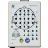
Reads a Mitsar-EEG 201 amplifier through a connector program from the vendor SDK, at 500 Hz.
| Port | Direction | Type | Meaning |
|---|---|---|---|
| EEG | Output | Channels | All 23 electrodes. |
| Fp1, Fpz, Fp2, F7, F3, Fz, F4, F8, T3, C3, Cz, C4, T4, T5, P3, Pz, P4, T6, O1, Oz, O2, A1, A2 | Output | Channels | One electrode per port. |
| Poly1, Poly2, Poly3, Poly4 | Output | Channels | Polygraphic channels. |
| Attribute | Values | Default | What it does |
|---|---|---|---|
| Upload, Device Number, Raw Output | See the shared table | Off, 1, Off | Shared device attributes. |
Availability: Windows only, with the connector from Mitsar. Status: Beta. Enable Mitsar Devices is off by default. See Biosensors.
Discovery 20
Section titled “Discovery 20”Reads a BrainMaster Discovery 20 amplifier through the vendor library, at 256 Hz.
| Port | Direction | Type | Meaning |
|---|---|---|---|
| EEG | Output | Channels | All 20 electrodes. |
| Fp1, F3, C3, P3, O1, F7, T3, T5, Fz, Fp2, F4, C4, P4, O2, F8, T4, T6, Cz, Pz, A2 | Output | Channels | One electrode per port. A code comment describes A2 as A2-A1. |
| Fpz, Oz, AUX23, AUX24 | Output | Channels | Additional inputs. They are not part of the EEG port. |
| Mode | Output | Channels | 0 during streaming, 1 during an impedance test. |
| Attribute | Values | Default | What it does |
|---|---|---|---|
| Upload, Device Number, Raw Output | See the shared table | Off, 1, Off | Shared device attributes. |
Availability: Windows x86 builds only, with bmrcm.dll from BrainMaster. Status: Beta. Enable BrainMaster Devices is on by default. The driver connects only when Code Key, Serial Number and Pass Key are set under NMStudio > Settings > Devices, group BrainMaster. See Biosensors.
eSense GSR
Section titled “eSense GSR”Provides skin response from a Mindfield eSense device.
| Port | Direction | Type | Meaning |
|---|---|---|---|
| GSR | Output | Channels | Skin response in µS, nominally 10 Hz. |
| Attribute | Values | Default | What it does |
|---|---|---|---|
| Upload, Device Number, Raw Output | See the shared table | Off, 1, Off | Shared device attributes. |
Status: Beta, Engine library only. Studio has no driver or OSC address for this device, so in Studio the node shows Device not connected and carries no data. Only a host application using the Engine library can feed it.
Notion
Section titled “Notion”Reads a Neurosity Notion 1 or Notion 2 headset through its OSC stream, at 250 Hz.
| Port | Direction | Type | Meaning |
|---|---|---|---|
| EEG | Output | Channels | All 8 electrodes. |
| CP5, F5, C3, CP3, CP6, F6, C4, CP4 | Output | Channels | One electrode per port. |
| Attribute | Values | Default | What it does |
|---|---|---|---|
| Upload, Raw Output | See the shared table | Off, Off | Shared device attributes. |
| Device Number | 1 or higher | 1 | Picks the device by its ID, which comes from the device string. Set it to the device ID shown in the Devices window plus 1. The default of 1 does not match a Neurosity device. |
Availability: all platforms. Status: Supported. There is no driver: the device appears when Studio receives the device’s OSC info message on the OSC input port. Other messages alone do not make it appear, and the info message decides between Notion and Crown. See Biosensors. Notion is also reachable through the BrainFlow node.
Reads a Neurosity Crown headset through its OSC stream, at 256 Hz.
| Port | Direction | Type | Meaning |
|---|---|---|---|
| EEG | Output | Channels | All 8 electrodes. |
| CP3, C3, F5, PO3, PO4, F6, C4, CP4 | Output | Channels | One electrode per port. |
| Attribute | Values | Default | What it does |
|---|---|---|---|
| Upload, Raw Output | See the shared table | Off, Off | Shared device attributes. |
| Device Number | 1 or higher | 1 | Picks the device by its ID, which comes from the device string. Set it to the device ID shown in the Devices window plus 1. The default of 1 does not match a Neurosity device. |
Availability: all platforms. Status: Beta. There is no driver: the device appears when Studio receives the device’s OSC info message on the OSC input port. Other messages alone do not make it appear, and the info message decides between Notion and Crown. Studio logs an error if the device’s info message reports another model, channel list or sample rate than it expects. See Biosensors.
BrainFlow
Section titled “BrainFlow”Connects to a board through the bundled BrainFlow library. The node creates the device itself, with no scan. Studio reads only EEG channels from BrainFlow.
| Port | Direction | Type | Meaning |
|---|---|---|---|
| EEG | Output | Channels | All EEG channels of the board. This port exists before anything connects, so seeing it does not mean the board is connected. |
| One port per channel | Output | Channels | Added after a board with more than one channel connects. Boards with no electrode names in BrainFlow get blank port labels, so identify them by order. |
| Attribute | Values | Default | What it does |
|---|---|---|---|
| Board ID | PlayBack, Streaming, Synthetic, Cyton, Ganglion, CytonDaisy, Galea, GanglionWifi, CytonWifi, CytonDaisyWifi, BrainBit, Unicorn, CallibriEEG, CallibriEMG, CallibriECG, Fascia, NotionOSC1, NotionOSC2, IronBCI, GforcePro, FreeEEG32 | Synthetic | The board to open. |
| Serial port | Text | Empty | Passed to BrainFlow. |
| MAC address | Text | Empty | Passed to BrainFlow. |
| IP address | Text | 192.168.4.1 | Passed to BrainFlow. |
| IP port | 1 to 65535 | 50000 | Passed to BrainFlow. |
| IP protocol | None, UDP, TCP | None | Passed to BrainFlow. |
| Other info | Text | Empty | Passed to BrainFlow. |
| Timeout | 0 or higher | 0 | Passed to BrainFlow. |
| Serial number | Text | Empty | Passed to BrainFlow. |
| File | Text | Empty | Passed to BrainFlow. |
| Apply | Button | Reads the fields and opens the board. Editing a field does nothing until you press it. |
Availability: compiled into every platform, not limited by account. Status: varies by board, see BrainFlow boards. Which boards work depends on the platform and vendor libraries. A name in the dropdown does not mean the board delivers data in Studio.
This node has no visible Upload, Device Number or Raw Output attribute. A saved classifier does not reconnect by itself, so press Apply again after you open one.
A fixed-board shortcut for the OpenBCI Cyton through BrainFlow. It is separate from the native OpenBCI node.
| Port | Direction | Type | Meaning |
|---|---|---|---|
| EEG | Output | Channels | All 8 EEG channels. |
| Fp1, Fp2, C3, C4, P7, P8, O1, O2 | Output | Channels | One channel per port, added after the board connects. |
| Attribute | Values | Default | What it does |
|---|---|---|---|
| Serial port | Text | COM3 on Windows, /dev/ttyUSB0 on Linux, /dev/cu.usbserial-DM0258D9 on macOS | The port to open. The macOS default is one specific dongle’s name, so most Mac users must change it. |
Availability: compiled into every platform, not limited by account. On macOS, the sandbox may block serial ports. Status: Supported. All other attributes are hidden, and there is no Apply button.
The node opens the port as soon as you add it, and again when you change the port. To keep the native OpenBCI scan off the same port, turn off NMStudio > Settings > Devices > Automatic Device Search. See The Cyton node for what happens on loading and removal.
Heartrate
Section titled “Heartrate”
Reads a Bluetooth LE heart rate sensor.
| Port | Direction | Type | Meaning |
|---|---|---|---|
| BPM | Output | Channels | Heart rate in beats per minute, at a variable rate. |
| RR-Interval | Output | Channels | Time between beats, at a variable rate. It is labelled ms and carries the raw sensor value, which standard Bluetooth LE heart rate sensors report in units of 1/1024 second. |
| Attribute | Values | Default | What it does |
|---|---|---|---|
| Upload, Device Number, Raw Output | See the shared table | Off, 1, Off | Shared device attributes. |
Availability: all platforms. Status: Supported. The only source is Studio’s Bluetooth driver, which is off by default. Tick Enable Bluetooth Devices under NMStudio > Settings > Devices > Drivers. A comment in the code warns that this driver stops working once the Versus driver is active. Leave Enable Senselabs Devices off when you use a heart rate sensor. See Bluetooth LE heart-rate sensors.
Accelerometer
Section titled “Accelerometer”
Provides three axes from a generic accelerometer.
| Port | Direction | Type | Meaning |
|---|---|---|---|
| X, Y, Z | Output | Channels | Acceleration per axis in m/s^2, nominally 50 Hz. |
| Attribute | Values | Default | What it does |
|---|---|---|---|
| Upload, Device Number, Raw Output | See the shared table | Off, 1, Off | Shared device attributes. |
Status: Beta, Engine library only. Studio has no driver or OSC address for this device, so in Studio the node shows Device not connected and carries no data. Only a host application using the Engine library can feed it.
Gyroscope
Section titled “Gyroscope”
Provides three axes from a generic gyroscope.
| Port | Direction | Type | Meaning |
|---|---|---|---|
| X, Y, Z | Output | Channels | Rotation per axis, nominally 10 Hz. The code gives the unit as rad/s^2. |
| Attribute | Values | Default | What it does |
|---|---|---|---|
| Upload, Device Number, Raw Output | See the shared table | Off, 1, Off | Shared device attributes. |
Status: Beta, Engine library only. Studio has no driver or OSC address for this device, so in Studio the node shows Device not connected and carries no data. Only a host application using the Engine library can feed it.
Gamepad
Section titled “Gamepad”Defines the inputs of a game controller.
| Port | Direction | Type | Meaning |
|---|---|---|---|
| Left X, Left Y, Right X, Right Y | Output | Channels | Joystick axes. |
| A, B, X, Y, L1, L2, L3, R1, R2, R3, Select, Start, Guide | Output | Channels | Buttons. |
| Up, Down, Left, Right, Center | Output | Channels | Directional buttons. |
| Attribute | Values | Default | What it does |
|---|---|---|---|
| Upload, Device Number, Raw Output | See the shared table | Off, 1, Off | Shared device attributes. |
Status: Beta, no data source found. Nothing in the code feeds gamepad state into this device, so the node shows Device not connected and carries no data.
Device nodes not in the public build
Section titled “Device nodes not in the public build”These nodes exist in the source but are not compiled into community builds, so they are not in the palette of a downloaded build. Vendor SDK licensing is not yet confirmed. See Devices.
- EPOC and Insight (Emotiv): Not in public build. Available through a source build (community) or a custom build (commercial clients). The vendor SDK is not in the repository.
- NeuroSky (NeuroSky MindWave): Not in public build. Available through a source build (community) or a custom build (commercial clients). The vendor SDK is not in the repository.
- EyeX (Tobii): Not in public build. Available through a source build (community) or a custom build (commercial clients). The vendor SDK is not in the repository.
- B-Alert X10 and B-Alert X24 (Advanced Brain Monitoring): Not in public build. Available through a source build (community) or a custom build (commercial clients). Windows 32-bit; vendor headers not in the repository.
- PET 4.0 (Brainquiry): Not in public build. Available through a source build (community) or a custom build (commercial clients). Windows 32-bit; vendor headers not in the repository.
- ActiChamp (Brain Products actiCHamp): Not in public build. Available through a source build (community) or a custom build (commercial clients). The source has only a driver skeleton with no data path, so a build must complete it.
Audio Input, Microphone and Audio Output nodes also exist in the source, with their flag turned off. They are not offered as device integrations.
Input Nodes
Section titled “Input Nodes”This category contains the nodes that generate their own data or get it from somewhere else, such as the file system, the network or the neuromore cloud. Device nodes are in the Sensors category.
A node in this category runs only while at least one of its outputs is connected.
Parameter
Section titled “Parameter”
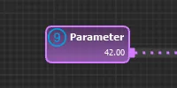
Outputs a value that you set. Use it for a fixed constant, or add a control to the Parameters window so the value can be changed during a session. A state machine can also find it by the name in its Node Name field and set it with the Parameter action. See State machine reference.
| Port | Direction | Type | Meaning |
|---|---|---|---|
| Show | Input | Channels | Shown only with Show Controls and Show Inputs on. The control is shown while the last sample is 1 or more, and hidden below that. Unconnected or empty means shown. |
| Enable | Input | Channels | Shown only with Show Controls and Show Inputs on. The control is enabled while the last sample is 1 or more, and disabled below that. Unconnected or empty means enabled. |
| Out | Output | Channels | The value, on every output channel. Channels take the node’s name. The port label shows the current value. |
| Attribute | Values | Default | What it does |
|---|---|---|---|
| Description | Text | Empty | Tooltip for the control in the Parameters window. |
| Value | Any number | 0 | The value to output. With Checkboxes, Dropdown Menu or Selection Buttons, it also picks the option selected at the start. Hidden for Separator (Dummy). |
| Sample Rate | 0 or higher | 0 | Rate of the output in Hz. 0 means automatic: the rate of the active BCI when the node starts, or 128 if there is none. Values below 0.01 count as 0. Hidden for Separator (Dummy). |
| Number of Channels | 1 or higher | 1 | Number of output channels. Hidden for Separator (Dummy). |
| Show Controls | On, off | Off | Adds a control for this node to the Parameters window. |
| Show Inputs | On, off | Off | Adds the Show and Enable input ports. Shown only with Show Controls on. |
| Control Type | Separator (Dummy), Value Slider, Checkboxes, Dropdown Menu, Selection Buttons, Event Buttons | Value Slider | The kind of control. Shown only with Show Controls on. |
| Range Min | Any number | 0 | Lower end of the slider. Shown only for Value Slider. |
| Range Max | Any number | 1 | Upper end of the slider. Shown only for Value Slider. |
| Options | Comma-separated list | OFF,ON | One entry per checkbox, menu item or button. Shown only for Checkboxes, Dropdown Menu, Selection Buttons and Event Buttons. |
What each control outputs:
| Control Type | Output |
|---|---|
| Separator (Dummy) | No value to set. Shows the node’s name in bold above a line, to group the other controls. |
| Value Slider | The slider value, on all channels. |
| Dropdown Menu | The index of the selected option, on all channels. The first option is 0. |
| Checkboxes, Selection Buttons | If Number of Channels equals the number of options, each channel is 1 or 0 for its own option. Otherwise only one option can be selected, and all channels output its index. The first option is 0. |
| Event Buttons | The value lasts for one sample, then returns to 0. If Number of Channels equals the number of options, a click sends 1 on that button’s channel. Otherwise all channels output the button’s position, starting at 1 for the first button. |
Range Min and Range Max limit the slider only. The node does not clamp a value set in another way, such as by the Parameter action.
Studio applies the state of each control when a session starts. When the classifier resets, the node returns to its Value attribute.
Signal Generator
Section titled “Signal Generator”
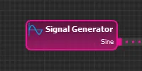
Generates periodic waveforms, noise or simulated brainwaves. Use it to build and check a classifier without a device.
| Port | Direction | Type | Meaning |
|---|---|---|---|
| Out | Output | Channels | The generated signal, one channel named after the node. The port label shows the signal type. |
| Attribute | Values | Default | What it does |
|---|---|---|---|
| Signal Type | Sine, Square, Noise, Ramp, Sawtooth, Triangle, Brainwaves | Sine | The signal to generate. See the next table. |
| Sample Rate | Above 0 | 128 | Rate of the output in Hz. |
| Frequency | Above 0 | 1 | Frequency of the waveform in Hz. For Ramp, see the next table. Hidden for Noise and Brainwaves. |
| Amplitude | 0 or higher | 1 | Size of the signal. See the next table. |
| DC-Offset | Any number | 0 | Added to the signal. Brainwaves does not use it. |
| Duty cycle | 0 or higher | 0.5 | Fraction of each period that the signal is high. 1 or more keeps it high. Shown only for Square. |
| Signal Type | Output |
|---|---|
| Sine | Swings from DC-Offset − Amplitude to DC-Offset + Amplitude. |
| Square | Starts each period high at DC-Offset + Amplitude, then drops to DC-Offset. |
| Noise | Random values from DC-Offset − Amplitude to DC-Offset + Amplitude. |
| Ramp | DC-Offset + Amplitude × time in seconds ÷ Frequency. It keeps rising and does not repeat. |
| Sawtooth | Rises from DC-Offset to DC-Offset + Amplitude each period, then jumps back. |
| Triangle | Rises from DC-Offset to DC-Offset + Amplitude and back down each period. |
| Brainwaves | A synthetic test signal, scaled by Amplitude: sine components around 0 to 3.5 Hz, 8 to 12 Hz and 13 to 16 Hz, with slowly varying strength, plus noise. It is not recorded EEG. |
Amplitude is half of peak-to-peak only for Sine and Noise. For Square, Sawtooth and Triangle it is the full peak-to-peak size.
OSC Input
Section titled “OSC Input”
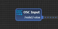
Receives float values over OSC from other programs on the network or on the same computer. Studio listens on UDP port 4545 by default. To change it, go to NMStudio > Settings > Network > OSC Server > Input UDP port. See OSC.
| Port | Direction | Type | Meaning |
|---|---|---|---|
| Out | Output | Channels | One channel with the received values. The port label shows the OSC address. |
| Attribute | Values | Default | What it does |
|---|---|---|---|
| OSC address | Text | /in/0, or the next free number | The address to listen to. A message must match it exactly. |
| Sample rate | Above 0 | 128 | The rate at which your source sends, in Hz. It describes the incoming data. Studio does not measure it. |
Every float argument in a matching message becomes one sample, and a message can carry several. The node does not hold the last value or add samples between messages, and it does not resample. Send at a steady rate and set Sample rate to that actual rate. Otherwise, nodes further along the classifier work on a wrong time base.
Send float arguments only. An argument of another type may arrive as 0.
If two OSC Input nodes in a classifier share an address, the node shows the error “OSC address is not unique” and does not run.
Session Info
Section titled “Session Info”Outputs the state of the running session: elapsed time, whether it is paused, and the points so far. Use this node for session timing in new classifiers.
| Port | Direction | Type | Meaning |
|---|---|---|---|
| Elapsed Time | Output | Channels | Session time in the selected Time Unit, without paused time. 0 when no session is running. |
| Paused | Output | Channels | 1 while the session is paused, otherwise 0. |
| Points | Output | Channels | Total from all Points nodes in the classifier. 0 when no session is running. |
| Attribute | Values | Default | What it does |
|---|---|---|---|
| Time Unit | Milliseconds, Seconds, Minutes, Hours | Seconds | Unit of the Elapsed Time output. |
| Sample Rate | 1 or higher | 128 | Rate of all three outputs in Hz. |
All samples created in one Engine update carry the same values, so the outputs move in small steps.
In 1.7.3: Points nodes keep accumulating during a pause, so the Points output can still rise while the session is paused.
Session Time
Section titled “Session Time”
Deprecated. Use Session Info in new classifiers. It is hidden from the palette. To add it, right-click in the graph and use the Add Node menu.
Outputs the time since the last reset of the classifier. It does not wait for the session to begin, so it can differ from Elapsed Time on Session Info.
| Port | Direction | Type | Meaning |
|---|---|---|---|
| Out | Output | Channels | The time in the selected Time Unit. The port label shows the unit. |
| Attribute | Values | Default | What it does |
|---|---|---|---|
| Time Unit | Milliseconds, Seconds, Minutes, Hours | Seconds | Unit of the output. |
| Sample Rate | 1 or higher | 128 | Rate of the output in Hz. |
During a session pause, samples keep flowing at the same rate and repeat the time at which the pause started. After Continue, the time counts on without the paused time.
In 1.7.3: The time keeps counting through a pause.
Cloud Input
Section titled “Cloud Input”
Reads values stored in the neuromore cloud. The Cloud Output node stores them when a session ends. Use the pair to carry a value from one session to the next.
The two nodes link through the node name. To read what a Cloud Output node stored, give the Cloud Input node exactly the same name and the same Type. With a different name, you get the Default Value. Set the name in the Node Name field of the node’s attributes. You can’t change it while a session is running.
| Port | Direction | Type | Meaning |
|---|---|---|---|
| Out | Output | Channels | The values read from the cloud, one channel named after the node. |
| Attribute | Values | Default | What it does |
|---|---|---|---|
| Default Value | Any number | 0 | Output until a stored value arrives, and if none exists. Used only when Sample Rate is above 0. |
| Sample Rate | 0 or higher | 128 | Rate of the output in Hz. See the behaviour below for 0. |
| Type | User Parameter, Classifier Parameter | User Parameter | User Parameter belongs to the user, so any classifier can read it. Classifier Parameter is requested with this classifier’s ID, so it is tied to this classifier. |
| Request Mode | Current Value (no history), Previous Values, All Values, Time Range | Current Value (no history) | What to ask the server for. See the next table. |
| Number of Values | 0 or higher | 10 | Intended as the number of values to request. The current code does not pass this value to the server: the request carries a limit of 0, and the result depends on the server. Shown only for Previous Values. |
| Time Range | Custom Range, One Hour, One Day, One Week, One Month, One Year | One Day | How far back to request values. One Month is 30 days and One Year is 365 days. Shown only for Time Range. |
| Time Range (Seconds) | 0 or higher | 1800 | Length of the custom range. Shown only for Time Range with Custom Range selected. |
| Request Mode | Requests |
|---|---|
| Current Value (no history) | One value. |
| Previous Values | Stored values, with a limit of 0 in the request, whatever Number of Values says. The result depends on the server. |
| All Values | All stored values. |
| Time Range | All stored values from the selected time range. |
Previous Values, All Values and Time Range ask for values saved with a timestamp. Cloud Output adds one only with Save Mode set to Save History.
Studio requests the values when you begin a session. If the request fails, the session does not start and Studio shows an error dialog.
What the node outputs depends on Sample Rate:
- Above 0: It outputs the Default Value until a reply arrives. After that it cycles through the returned values in a loop, one per sample. With a single returned value, such as from Current Value (no history), the output stays at that value for the session.
- 0: It outputs each returned value once and does not repeat it. It outputs nothing before a reply arrives.
Messages on the node:
- The warning “Not Updated.” means the node has no stored value yet.
- The error “Name is not unique.” means another Cloud Input node in the classifier has the same name.
File Reader
Section titled “File Reader”
Reads a multichannel data file from the local file system and plays it back in a loop. It loads the whole file when the node starts.
| Port | Direction | Type | Meaning |
|---|---|---|---|
| Out | Output | Channels | One channel per column or signal in the file. The port label shows the file path. |
| Attribute | Values | Default | What it does |
|---|---|---|---|
| File | Text | Empty | Path of the data file on the local computer. Use a full path. |
| Format | CSV (*.csv), CSV with timestamps (*.csv), EDF(+) / BDF(+) (*.edf) | CSV (*.csv) | The format of the file. |
| Sample Rate | 0 or higher | 0 | Overrides the rate of all channels, in Hz. Fractions are dropped. 0 uses the rate from the file. |
CSV files are comma-separated:
Fp1,Fp2256Hz,256Hz10.5,-3.211.0,-2.9- The first line holds the channel names.
- The second line is optional and holds the sample rates. Studio treats it as a rate line if it contains “Hz”, “hz”, “Samplerate” or “samplerate”.
- Every other line holds one value per channel, so avoid blank lines. A line can be up to 4,095 characters long.
- In CSV with timestamps, Studio ignores the first column. It does not use the timestamps for timing.
For EDF and BDF files:
- Annotations are not read.
- A label that contains “EEG”, such as “EEG Fp1”, becomes the second word, “Fp1”.
- Studio uses the signal’s samples per data record as the rate. This equals Hz only when a data record lasts 1 second. For other files, set Sample Rate.
When the node produces nothing or stops with a message:
- No rate: If the file gives no sample rate and Sample Rate is 0, the node outputs no samples and shows no error.
- Mixed rates: If channels have different rates and Sample Rate is 0, the node does not run and shows no error. Set Sample Rate to run it. All channels then play at that rate.
- “No file specified.” The File attribute is empty.
- “Cannot open file.” The path is wrong or the file cannot be read.
- “Can’t parse the file. Wrong format?” The content does not match Format, or a line has the wrong number of values or a value that is not a number.
- “File is empty.” The file contains no samples. This is a warning.
If channels differ in length, playback loops at the length of the shortest channel.
Output Nodes
Section titled “Output Nodes”This category holds the nodes that take data out of the classifier: to visualizations, the network, the neuromore cloud, files, Studio’s windows and audio. None of them has an output port.
Custom Feedback, Body Feedback, OSC Output, Points, the Volume, Brightness, Speed, Sun, Clouds, Fog, Rain and Vignette Control nodes share the attributes below. They use only the first channel of a multi-channel input.
| Attribute | Values | Default | What it does |
|---|---|---|---|
| Resolution | Original (the input’s sample rate), High (30 Hz), Mid (10 Hz), Low (4 Hz) | High | Sets the sample rate of the node’s output channel. This changes the size of uploaded data, the packet rate of OSC Output and the curve in the Feedback window. The feedback bundle and WebSocket frames always use the latest input value, so their rate doesn’t change. |
| Upload | On, off | Off | Adds the node’s output to the data Studio uploads after the session stops. Whether data is uploaded also depends on your account. See the Privacy Policy. |
| Output Name | Use Node Name, Use Channel Name, Use Custom Name | Use Node Name | Sets the name of the output channel. |
| Custom Name | Text | Empty | The name to use. Shown only with Use Custom Name. If it is empty, the node’s name is used. |
On the Volume, Brightness, Speed, Sun, Clouds, Fog, Rain and Vignette Control nodes, the Custom Name field does not appear, so Use Custom Name gives the node’s name.
In 1.7.3: Output Name has only Use Node Name and Use Channel Name, and there is no Custom Name.
Send OSC Msgs puts a node’s value in the feedback bundle on port 45554, not on 4546. Each message has four arguments: value (float), is ranged (bool), range min (float), range max (float). OSC Output nodes use port 4546.
Custom Feedback
Section titled “Custom Feedback”
The default node for a classifier’s main results, such as a calculated metric or the feedback path. Its value appears in the Feedback window and goes out in WebSocket frames while a session runs. It reaches visualizations only with Send OSC Msgs on, and the neuromore cloud only with Upload on. Both are off by default.
| Port | Direction | Type | Meaning |
|---|---|---|---|
| In | Input | Channels | The feedback value. |
| Attribute | Values | Default | What it does |
|---|---|---|---|
| Resolution, Upload, Output Name, Custom Name | See the shared table | High, Off, Use Node Name, Empty | Shared output attributes. |
| Send OSC Msgs | On, off | Off | Sends the value in the feedback bundle on port 45554. |
| OSC Address | Text | /feedback/0, then the next free number |
The address of the message. Shown only with Send OSC Msgs on. |
| User ID | 0 or higher | 0 | Stored with the node. Studio does not use this value. |
| Is Ranged | On, off | On | Checks the value against Range Min and Range Max. Also sent as the second OSC argument. |
| Range Min | Any number | 0 | Lowest expected value. Shown only with Is Ranged on. Sets the lower limit of the output channel. |
| Range Max | Any number | 1 | Highest expected value. Shown only with Is Ranged on. Sets the upper limit of the output channel. |
Range Min and Range Max don’t clamp the value. With Is Ranged on, a value outside the range puts the error “Value not in range” on the node, and the raw value is still sent. To keep a value in range, put a Remap node with Clamp Output on in front of this node.
Two nodes that send to the same address give the error “OSC address is not unique”. A Custom Feedback node named Volume or MasterVolume gets a deprecation warning and has no effect on volume. Use Volume Control instead.
Body Feedback
Section titled “Body Feedback”
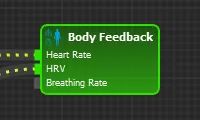
Sends heart rate, HRV and breathing rate to visualizations. Deprecated. For new classifiers, use Custom Feedback nodes. It is hidden from the palette, and existing classifiers can still use it. To add it, right-click in the graph and use the Add Node menu.
| Port | Direction | Type | Meaning |
|---|---|---|---|
| Heart Rate | Input | Channels | Heart rate in BPM. Sent to /heartrate. |
| HRV | Input | Channels | Heart rate variability in ms. Sent to /hrv. |
| Breathing Rate | Input | Channels | Breathing rate in BPM. Sent to /breathingrate. |
| Attribute | Values | Default | What it does |
|---|---|---|---|
| Resolution, Upload, Output Name, Custom Name | See the shared table | High, Off, Use Node Name, Empty | Shared output attributes. |
| Send OSC Msgs | On, off | Off | Sends the three values in the feedback bundle on port 45554. Unlike other feedback nodes, each message has one float argument, and it comes from the output channel, so Resolution applies. |
| User ID | 0 or higher | 0 | Stored with the node. Studio does not use this value. |
The node doesn’t appear in the Feedback window and isn’t sent over WebSocket.
OSC Output
Section titled “OSC Output”
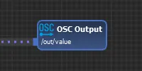
Sends a value to another program as a plain OSC message with one float argument. The default target is 127.0.0.1, UDP port 4546. Change it in NMStudio > Settings > Network > OSC Server > Target Host/IP and Target UDP port. See OSC.
| Port | Direction | Type | Meaning |
|---|---|---|---|
| The node’s OSC address | Input | Channels | The value to send. The port takes its name from OSC Address. |
| Attribute | Values | Default | What it does |
|---|---|---|---|
| Resolution, Output Name, Custom Name | See the shared table | High, Use Node Name, Empty | Shared output attributes. Resolution sets the rate: one packet per output sample, so 30 packets per second at High. |
| OSC Address | Text | /out/0, then the next free number |
The address of the message. |
Upload is hidden on this node. Two OSC Output nodes with the same address give the error “OSC address is not unique”, and the node stops.
Points
Section titled “Points”
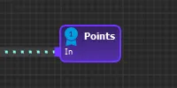
Gives the session a score. Points appear in the Session Control window during a session and in the Points output of the Session Info node. They are also sent in the feedback bundle as /session/points. With several Points nodes, the session score is their sum.
| Port | Direction | Type | Meaning |
|---|---|---|---|
| In | Input | Channels | The value to score. |
| Attribute | Values | Default | What it does |
|---|---|---|---|
| Output Name, Custom Name | See the shared table | Use Node Name, Empty | Shared output attributes. |
| Points Multiplier | 0 to 10000, whole numbers | 0 | Chooses how points are calculated. See below. |
Points Multiplier sets the mode:
- 0, the default: the score is the latest input value. Nothing is added up over time, and the value isn’t clamped.
- Above 0: the score adds up over time. Each sample is clamped to 0..1 and adds value × multiplier × sample duration. An input of 1 earns the multiplier’s value in points per second. Nothing is added while the session is paused.
Resolution and Upload are hidden on this node.
In 1.7.3: With a multiplier above 0, points keep adding up during a pause.
Cloud Output
Section titled “Cloud Output”
Stores a single value in the neuromore cloud. The Cloud Input node can read it back. The parameter name is the node’s name.
| Port | Direction | Type | Meaning |
|---|---|---|---|
| In | Input | Channels | The value to store. Must be a single channel. |
| Attribute | Values | Default | What it does |
|---|---|---|---|
| Type | User Parameter, Classifier Parameter | User Parameter | Classifier Parameter ties the value to this classifier. |
| Save Mode | Overwrite Value, Save History | Overwrite Value | Save History stores the value with the session’s stop time. |
Studio writes the last input value when the session stops, including when it stops a session automatically, for example after losing a device. If the node has no value, nothing is written.
Errors: “Name is not unique.” when two Cloud Output nodes share a name, and “Input has too many channels. Node requires a single channel.” for a multi-channel input.
Volume Control
Section titled “Volume Control”Sets a volume from a value between 0 and 1. The range is fixed. A value outside it puts the error “Value not in range” on the node and isn’t clamped. To keep a value in range, put a Remap node with Clamp Output on in front of this node.
Volume Control works in Studio’s Experience window and over WebSocket to the Chrome extension. In Visualization mode, it sends
/audio/volumeto visualizations in the feedback bundle on port 45554.
Note: Not every build sends
/audio/volumeyet. 1.7.3 and the current 1.8.2 source don’t. In those builds, use a Custom Feedback node with the OSC address/audio/volumeand Send OSC Msgs on.
| Port | Direction | Type | Meaning |
|---|---|---|---|
| In | Input | Channels | The volume, from 0 to 1. |
| Attribute | Values | Default | What it does |
|---|---|---|---|
| Resolution, Upload, Output Name | See the shared table | High, Off, Use Node Name | Shared output attributes. |
| Mode | Studio Volume, Overall System Volume, Single Media File, Tone, Visualization | Studio Volume | What the value controls. See below. |
| File | Text | Empty | The media file to control. Shown in Single Media File mode. |
| Node | Text | Empty | The name of the Tone Generator node to control. Shown in Tone mode. |
| Mode | What it controls |
|---|---|
| Studio Volume | All media in the Experience window. Only the first node in this mode acts. |
| Overall System Volume | The computer’s master volume. Windows builds only. It is skipped if a Single Media File node comes first. |
| Single Media File | The media file named in File. |
| Tone | The Tone Generator named in Node. |
| Visualization | Turns on the node’s OSC message to visualizations. It has no effect in the Experience window. |
Mode doesn’t affect the WebSocket path. The value goes to the Chrome extension in every mode. The extension matches the name exactly, so keep the name Volume Control. See Chrome extension.
Brightness Control
Section titled “Brightness Control”Sets brightness from a value between 0 and 1. In the Experience window, a black overlay covers the content with an opacity of 1 minus the value, so 1 is full brightness and 0 is black. The range is fixed. A value outside it puts the error “Value not in range” on the node.
Brightness Control works in Studio’s Experience window and over WebSocket to the Chrome extension. It sends no OSC, deliberately, and games have no brightness address.
| Port | Direction | Type | Meaning |
|---|---|---|---|
| In | Input | Channels | The brightness, from 0 to 1. |
| Attribute | Values | Default | What it does |
|---|---|---|---|
| Resolution, Upload, Output Name | See the shared table | High, Off, Use Node Name | Shared output attributes. |
The Chrome extension matches the name exactly, so keep the name Brightness Control.
Speed Control
Section titled “Speed Control”Controls movement speed in a visualization. Sends a value between 0 and 1 to the fixed address /movement-speed in the feedback bundle on port 45554. Send OSC Msgs is always on and there is no address to set. Read by Cartoon Town, Forest Walk and Infinite Tunnel. See Visualizations.
| Port | Direction | Type | Meaning |
|---|---|---|---|
| In | Input | Channels | The value, from 0 to 1. |
| Attribute | Values | Default | What it does |
|---|---|---|---|
| Resolution, Upload, Output Name | See the shared table | High, Off, Use Node Name | Shared output attributes. |
The range is fixed. A value outside it puts the error “Value not in range” on the node and is still sent.
Sun Control
Section titled “Sun Control”Controls sunlight in a visualization. Sends a value between 0 and 1 to the fixed address /weather-sun in the feedback bundle on port 45554. Send OSC Msgs is always on and there is no address to set. Read by Cartoon Town, Forest Walk and Tropical Island. See Visualizations.
| Port | Direction | Type | Meaning |
|---|---|---|---|
| In | Input | Channels | The value, from 0 to 1. |
| Attribute | Values | Default | What it does |
|---|---|---|---|
| Resolution, Upload, Output Name | See the shared table | High, Off, Use Node Name | Shared output attributes. |
The range is fixed. A value outside it puts the error “Value not in range” on the node and is still sent.
Clouds Control
Section titled “Clouds Control”Controls clouds in a visualization. Sends a value between 0 and 1 to the fixed address /weather-clouds in the feedback bundle on port 45554. Send OSC Msgs is always on and there is no address to set. Read by Forest Walk. See Visualizations.
| Port | Direction | Type | Meaning |
|---|---|---|---|
| In | Input | Channels | The value, from 0 to 1. |
| Attribute | Values | Default | What it does |
|---|---|---|---|
| Resolution, Upload, Output Name | See the shared table | High, Off, Use Node Name | Shared output attributes. |
The range is fixed. A value outside it puts the error “Value not in range” on the node and is still sent.
Fog Control
Section titled “Fog Control”Controls fog in a visualization. Sends a value between 0 and 1 to the fixed address /weather-fog in the feedback bundle on port 45554. Send OSC Msgs is always on and there is no address to set. Read by Forest Walk. See Visualizations.
| Port | Direction | Type | Meaning |
|---|---|---|---|
| In | Input | Channels | The value, from 0 to 1. |
| Attribute | Values | Default | What it does |
|---|---|---|---|
| Resolution, Upload, Output Name | See the shared table | High, Off, Use Node Name | Shared output attributes. |
The range is fixed. A value outside it puts the error “Value not in range” on the node and is still sent.
Rain Control
Section titled “Rain Control”Controls rain in a visualization. Sends a value between 0 and 1 to the fixed address /weather-rain in the feedback bundle on port 45554. Send OSC Msgs is always on and there is no address to set. Read by Cartoon Town, Forest Walk and Tropical Island. See Visualizations.
| Port | Direction | Type | Meaning |
|---|---|---|---|
| In | Input | Channels | The value, from 0 to 1. |
| Attribute | Values | Default | What it does |
|---|---|---|---|
| Resolution, Upload, Output Name | See the shared table | High, Off, Use Node Name | Shared output attributes. |
The range is fixed. A value outside it puts the error “Value not in range” on the node and is still sent.
Vignette Control
Section titled “Vignette Control”Controls the camera vignette in a visualization. Sends a value between 0 and 1 to the fixed address /camera/vignetting in the feedback bundle on port 45554. Send OSC Msgs is always on and there is no address to set. Read by all four visualizations. See Visualizations.
| Port | Direction | Type | Meaning |
|---|---|---|---|
| In | Input | Channels | The value, from 0 to 1. |
| Attribute | Values | Default | What it does |
|---|---|---|---|
| Resolution, Upload, Output Name | See the shared table | High, Off, Use Node Name | Shared output attributes. |
The range is fixed. A value outside it puts the error “Value not in range” on the node and is still sent.
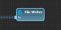
File Writer
Section titled “File Writer”
Writes its input channels to a local file while a session runs. Data goes to the file about 10 times per second. The File Reader node can read these files back.
| Port | Direction | Type | Meaning |
|---|---|---|---|
| In | Input | Channels | The channels to write. All must have matching sample rates. |
| Attribute | Values | Default | What it does |
|---|---|---|---|
| File | Text | Empty | The path of the output file. $starttime in the path is replaced by the session’s start time. On Windows, a leading ~ means your user folder. |
| Format | CSV, CSV with timestamps, EDF+ | CSV | The file format. |
| Write Mode | Never Overwrite, Overwrite | Overwrite | What happens if the file already exists. |
| EDF+ Min. | -10000 to -1 | -100 | Physical minimum in the EDF+ header, in µV. |
| EDF+ Max. | 1 to 10000 | 100 | Physical maximum in the EDF+ header, in µV. |
Caution: Write Mode defaults to Overwrite, so a session replaces an existing file with the same name. To keep earlier recordings, use Never Overwrite or put
$starttimein the path.
With Never Overwrite and an existing file, the node shows the error “File already exists.” and writes nothing. Appending isn’t available.
CSV files start with a line of channel names and a line of sample rates. CSV with timestamps adds a first column with each sample’s time in seconds.
EDF+ takes at most 64 channels and 512 Hz, and all channels need the same sample rate. The header labels the unit as µV.
Other errors: “Cannot open file for writing.” for an empty or unusable path, “Cannot write to file.” when writing fails, “Cannot configure the file.” when the EDF+ header can’t be set up, and “Input sample rates are incompatible.” when sample rates differ.

Shows signals in the Signal View window and spectra in the Spectrum View window. It affects only the display.
| Port | Direction | Type | Meaning |
|---|---|---|---|
| In | Input | Channels | Signals for the Signal View window. |
| In (Spectrum) | Input | Spectrum | Spectra for the Spectrum View window. |
| Enable | Input | Channels | If connected, the node shows data only while the value is 1 or more. If not connected, the node is always on. |
| Length in mins | Input | Channels | The fixed time range in minutes. Must be above 0. Shown only with Fixed Length in mins on. |
| Attribute | Values | Default | What it does |
|---|---|---|---|
| Scaling | Auto (Peak), Auto (StdDev), Custom Range | Auto (Peak) | How the In signals are scaled. Auto (Peak) uses the lowest and highest value in the displayed time. Auto (StdDev) uses the mean plus or minus half a standard deviation. |
| Range Min | Any number | 0 | Lower limit. Shown only with Custom Range. |
| Range Max | Any number | 1 | Upper limit. Shown only with Custom Range. |
| Custom Color | On, off | Off | Uses Color for the signal. |
| Color | Color | neuromore blue | The signal color. Shown only with Custom Color on. |
| Combined View | On, off | Off | Shows all input channels in one chart. |
| Fixed Length in mins | On, off | Off | Shows the Length in mins port. Its unit is minutes. |
With a value on Length in mins, the view shows that fixed time range. Without one, the time range comes from the Signal View window. The input channels must be synchronized to the engine. Otherwise the node shows the error “Input channel is not synchronized to engine.”
In 1.7.3: There is no Length in mins port and no Fixed Length in mins attribute.
Tone Generator
Section titled “Tone Generator”Plays a sound from values alone, with no audio file. Studio plays it on the default audio output device while the Experience window is open. To change its volume, use a Volume Control node in Tone mode, with the Tone Generator’s name in Node.
| Port | Direction | Type | Meaning |
|---|---|---|---|
| Instrument | Input | Channels | 0 sine wave, 1 clarinet, 2 flute, 3 guitar, 4 sitar. Not connected means sine wave. |
| Frequency | Input | Channels | The tone’s frequency in Hz. Required: no sound without it. |
| Amplitude | Input | Channels | How strongly a note is played. Not connected means 1. Clarinet and flute cap it at 1. It has no effect on the sine wave. |
| Delay | Input | Channels | Seconds between new notes, or between frequency updates for the sine wave. Not connected means 1. |
| Enabled | Input | Channels | Plays while the value is 1 or more. Not connected means always on. |
This node has no attributes. The input channels must be synchronized to the engine. Otherwise the node shows the error “Input channel is not synchronized to engine.”
Math Nodes
Section titled “Math Nodes”This category contains mathematical functions and methods: Function, Operation, Compare, Logic, Remap, Channel Math, Statistics and Integral. Threshold and Auto Threshold are in the Bio category.
A node with no connected input does not run.
Function, Operation, Compare, Logic, Remap, Statistics and Integral process each channel separately, so they output one channel for each input channel. On nodes with several inputs, a port with one channel is paired with every channel of the other port. Two ports with several channels must have the same number of channels. Otherwise the node reports “Sizes of input multichannels are incompatible.” Mixing channels from synchronized and independent sources gives the error “Input channels are incompatible. Must be either synced or independent.”
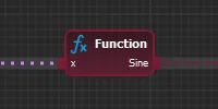
Function
Section titled “Function”
Applies a mathematical function to every sample of its input, for example sine() or abs().
| Port | Direction | Type | Meaning |
|---|---|---|---|
| x | Input | Channels | The input value. |
| Output (named after the function, Sine by default) | Output | Channels | The result, at the same sample rate as the input. |
| Attribute | Values | Default | What it does |
|---|---|---|---|
| Math Function | See the table below | Sine | The function applied to x. |
| Math Function | Output |
|---|---|
| Sine, Cosine, Tan | The trigonometric function, with x in radians. |
| Square | x × x |
| Square Root | √x. Outputs 0 if x is 0.000001 or less. |
| Absolute | The value of x without its sign. |
| Floor, Ceil | x rounded down, or rounded up, to a whole number. |
| One Over X | 1 / x. Outputs 0 if x is 0.000001 or less, so negative inputs also give 0. |
| Inverse Square Root | 1 / √x. Outputs 0 if x is 0.000001 or less. |
| Natural Log, Log Base 10 | The logarithm of x. Outputs 0 if x is 0.000001 or less. |
| Exponent | e to the power of x. |
| Fraction | The part of x after the decimal point. It keeps the sign of x. |
| Sign | -1 if x is negative, 1 if x is positive, 0 if x is 0. |
| Is Positive | 1 if x is 0 or greater, otherwise 0. |
| Is Negative | 1 if x is below 0, otherwise 0. |
| Is Near Zero | 1 if x is between -0.000001 and 0.000001, otherwise 0. |
| Random Float | A new random number between 0 and x for each sample. |
| Radians to Degrees, Degrees to Radians | x converted between the two units. |
| Smooth Step Cosine [0..1] | x limited to 0 to 1, then (1 - cos(π × x)) / 2. |
| Smooth Step Poly [0..1] | x limited to 0 to 1, then x² × (3 - 2 × x). |
| Arc Cosine, Arc Sine, Arc Tan | The inverse trigonometric function, in radians. |
Any result that is not a valid number outputs 0. This includes Arc Cosine and Arc Sine of a value outside -1 to 1.
In 1.7.3: Invalid results are passed on as they are, not replaced by 0. For inputs above 1, Smooth Step Poly returns 3 - 2 × input, not 1.
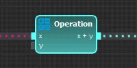
Operation
Section titled “Operation”
Combines two values, for example by adding or multiplying them.
| Port | Direction | Type | Meaning |
|---|---|---|---|
| x | Input | Channels | First value. |
| y | Input | Channels | Second value. |
| Output (named after the function, x + y by default) | Output | Channels | The result. |
Connect at least one of x and y. Second Value stands in for the other.
| Attribute | Values | Default | What it does |
|---|---|---|---|
| Math Function | Add, Subtract, Multiply, Divide, Average, Random Float, Mod, Minimum, Maximum, Power | Add | The operation to apply. |
| Second Value | Any number | 1 | Used for x or y when that port has no connection. |
| Math Function | Output port name | Output |
|---|---|---|
| Add | x + y | The sum. |
| Subtract | x - y | The difference. |
| Multiply | x * y | The product. |
| Divide | x / y | The quotient. Outputs 0 if y is within 0.000001 of 0. |
| Average | Average | (x + y) / 2 |
| Random Float | Random[x..y] | A new random number between x and y for each sample. |
| Mod | x MOD y | The remainder of x / y, with the sign of x. Outputs 0 if y is within 0.000001 of 0. |
| Minimum | Min(x, y) | The smaller value. |
| Maximum | Max(x, y) | The larger value. |
| Power | Pow(x, y) | x to the power of y. Outputs 0 if x is within 0.000001 of 0 and y is negative, or if x is negative and y is not a whole number. |
If both ports are connected, they need the same sample rate, or exactly one of them must be non-uniform (sample rate 0). Otherwise the node reports “Input sample rates are incompatible.” Two non-uniform channels also give this error. A non-uniform channel works as a held value: the node uses its last received sample, or Second Value until a first sample arrives. The output runs at the rate of the other channel.
In 1.7.3: A negative x with a non-integer y is not caught, so Power outputs an invalid number, not 0.
Compare
Section titled “Compare”
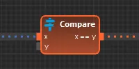
Compares two values and outputs a value based on the result. You can compare two channels, or one channel against a fixed value.
| Port | Direction | Type | Meaning |
|---|---|---|---|
| x | Input | Channels | First value. |
| y | Input | Channels | Second value. |
| Output (named after the function, x == y by default) | Output | Channels | The result, chosen by the return modes. |
| Attribute | Values | Default | What it does |
|---|---|---|---|
| Function | Equal to (x == y), Greater than (x > y), Less than (x < y), Grt. or Equal (x >= y), Less or Equal (x <= y), Inequal to (x != y) | Equal to (x == y) | The comparison to make. |
| Second Value | Any number | 0 | Used for x or y when that port has no connection. |
| True Return Mode | Return True Value, Return X, Return Y | Return True Value | What to output when the comparison is true. |
| Result when True | Any number | 1 | The output when the comparison is true. Shown only with Return True Value. |
| False Return Mode | Return False Value, Return X, Return Y | Return False Value | What to output when the comparison is false. |
| Result when False | Any number | 0 | The output when the comparison is false. Shown only with Return False Value. |
Equal to and Inequal to treat two values as equal when they are within 0.000001 of each other. If both ports are connected, they need the same sample rate. Otherwise the node reports “Input sample rates are incompatible.”

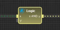
Provides boolean operations. An input of exactly 0 counts as false, and every other value counts as true.
| Port | Direction | Type | Meaning |
|---|---|---|---|
| x | Input | Channels | First value. |
| y | Input | Channels | Second value. |
| Output (named after the function, x AND y by default) | Output | Channels | Float Result when True or Float Result when False. |
| Attribute | Values | Default | What it does |
|---|---|---|---|
| Logic Function | AND, OR, XOR | AND | The logic function to use. |
| Second Value | False, True | False | Intended for x or y when that port has no connection. See the note below. |
| Float Result when True | Any number | 1 | The output when the expression is true. |
| Float Result when False | Any number | 0 | The output when the expression is false. |
The code does not apply the Second Value setting. An unconnected port always counts as false, even with True selected. So with only one port connected, AND always gives the false result, and the result of OR and XOR depends only on the connected input. To get a true second value, connect a Parameter node to the port, with Value set to 1 and Sample Rate set to the rate of the other input.
If both ports are connected, they need the same sample rate. Otherwise the node reports “Input sample rates are incompatible.”

Maps a value from one range to another with a linear transform.
| Port | Direction | Type | Meaning |
|---|---|---|---|
| x | Input | Channels | The value to remap. Required. Studio can show the input range as this port’s name, for example [0, 1]. |
| In Max | Input | Channels | Replaces Input Max when connected. |
| In Min | Input | Channels | Replaces Input Min when connected. |
| Out Max | Input | Channels | Replaces Output Max when connected. |
| Out Min | Input | Channels | Replaces Output Min when connected. |
| Out | Output | Channels | The remapped value. Studio can show the output range as this port’s name. |
| Attribute | Values | Default | What it does |
|---|---|---|---|
| Input Min | Any number | 0 | This input value maps to Output Min. |
| Input Max | Any number | 1 | This input value maps to Output Max. |
| Output Min | Any number | 0 | The output for an input of Input Min. |
| Output Max | Any number | 1 | The output for an input of Input Max. |
| Clamp Output | On, off | Off | Limits the output to the range between Output Min and Output Max. |
With Clamp Output off, values outside the input range are not clipped. They continue along the same line, so the output can go beyond Output Min and Output Max. For example, with an input range of 0 to 1 and an output range of 0 to 100, an input of 2 gives 200. With Clamp Output on, the same input gives 100.
If Input Min and Input Max are within 0.000001 of each other, the output is Output Min. All connected ports need the same sample rate. Otherwise the node reports “Input sample rates are incompatible.”
Channel Math
Section titled “Channel Math”
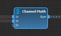
Applies a mathematical operation across several channels, for example to calculate the average of a list of signals. The result is one output channel.
| Port | Direction | Type | Meaning |
|---|---|---|---|
| In | Input | Channels | Input channels. Every channel on every connected port counts. Ports are added as you connect signals, and one free port stays available. Unneeded free ports at the end are removed. |
| Output (named after the function, Sum by default) | Output | Channels | One channel with the result, at the input sample rate. |
| Attribute | Values | Default | What it does |
|---|---|---|---|
| Math Function | Sum, Product, Average, Minimum, Maximum, Harmonic Mean, Geometric Mean, Root Mean Square, Sum of Squares | Sum | The function applied to the channels, one set of samples at a time. |
Harmonic Mean outputs 0 if any value is within 0.000001 of 0, or if the reciprocals of the values add up to about 0. Geometric Mean outputs 0 if any value is 0 or negative.
All input channels need the same sample rate. Otherwise the node reports “Input sample rates are incompatible.”
In 1.7.3: Geometric Mean checks only the product of the values, so an even number of negative values gives a result other than 0. Harmonic Mean outputs 0 only when a value is exactly 0 or the reciprocals add up to exactly 0.
Statistics
Section titled “Statistics”
Calculates a statistic of each channel over an interval in the time domain.
| Port | Direction | Type | Meaning |
|---|---|---|---|
| In | Input | Channels | The values to analyse. |
| Output (named after the statistic, Mean by default) | Output | Channels | The statistic over the interval. |
| Attribute | Values | Default | What it does |
|---|---|---|---|
| Interval Type | Duration, Sample Count | Duration | Whether you set the interval in seconds or in samples. |
| Length (Seconds) | 0 or higher | 1 | The interval length. Shown only with Duration. |
| Length (Samples) | 0 or higher | 100 | The interval length. Shown only with Sample Count. |
| Statistic | See the table below | Mean | The statistic to calculate. |
| Percentile | 0 to 100 | 95 | Which percentile to calculate. Shown only with the Percentile statistic. Any fractional part is dropped. |
| Epoching | On, off | Off | Off gives one result per input sample, over a sliding interval, at the input sample rate. Disable epoching if you want fast feedback. On gives one result per complete interval, with no overlap, at the input sample rate divided by the number of samples in the interval. |
| Zero Padding | On, off | Off | Controls what the node outputs before a full interval has arrived. With Epoching Off: Off outputs 0. On outputs results straight away. Early results can be calculated with zeros in place of samples not yet read, so they are approximate. With Epoching On, the first result arrives after one full interval but doesn’t yet cover one: it is 0 with Zero Padding Off, and calculated mostly from zeros with Zero Padding On. Later results each cover a full interval, ending about one interval before the newest sample. |
| Statistic | Output port name | Result |
|---|---|---|
| Minimum | Min | The smallest value. |
| Maximum | Max | The largest value. |
| Range | Range | Largest minus smallest value. |
| Mean | Mean | The average. |
| Median | Median | The middle value. With an even number of samples, the average of the two middle values. |
| Variance | Variance | The sample variance, dividing by the number of samples minus 1. Outputs 0 for a single sample. |
| Standard Deviation | Std.Dev. | The square root of Variance. |
| RMS | Unknown | The root mean square. The port name reads Unknown for this statistic. |
| Percentile | P | The chosen percentile, interpolated linearly between the two nearest values. |
| Sum of Elements | Sum | The sum. |
| Product of Elements | Product | The product. |
| Harmonic Mean | Harm. | The number of samples divided by the sum of the reciprocals. Outputs 0 if any value is exactly 0. |
| Geometric Mean | Geom. | The nth root of the product, for n samples. Outputs 0 if the product is 0 or negative. |
With Duration, the interval has as many samples as the sample rate times Length (Seconds), rounded up. The input must have a fixed sample rate, otherwise the node reports “Input must have a valid sample rate.” Sample Count has no such check.
A length of 0 gives an empty interval, and the node does not start, so it has no output.
While a session is paused, the node keeps reading samples but outputs the last value calculated before the pause. See Running a session.
In 1.7.3: Statistics keeps calculating during a pause. Variance and Standard Deviation divide by the number of samples, not by the number of samples minus 1. Median and Percentile pick one sorted value and do not interpolate. Product of Elements and Geometric Mean always output 0. Protocols tuned on 1.7.3 can behave differently. See What changed since 1.7.3.
Integral
Section titled “Integral”Adds up its input over time, as a running total. It sums each sample divided by the sample rate, so a constant input of 1 grows by 1 per second. The node is useful for scores that build up over a session.
| Port | Direction | Type | Meaning |
|---|---|---|---|
| In | Input | Channels | The value to integrate. It must have a fixed sample rate, otherwise the node reports “Input must have a valid sample rate.”. |
| Out | Output | Channels | The running total, one output sample per input sample. |
The node has no attributes. The total starts at 0 and returns to 0 when the node reinitialises.
While a session is paused, the node keeps reading samples but does not add them, and it keeps outputting the same total. See Running a session.
In 1.7.3: The total keeps growing during a pause.
DSP Nodes
Section titled “DSP Nodes”This category contains the digital signal processing nodes: spectrum analysis, filters and signal generators. All of them are in the DSP tab of the palette except Select Bins, which you add from the right-click menu.
Nodes that process a signal run once per input channel, so a multichannel input gives a multichannel output.

Calculates a one-sided magnitude spectrum from each epoch of the input signal. Use it in front of Frequency Band, Dominant Frequency or Select Bins. The output is a magnitude spectrum, not a power spectral density.
| Port | Direction | Type | Meaning |
|---|---|---|---|
| In | Input | Channels | Signal to analyse. It needs a constant sample rate. |
| Out (Spectrum) | Output | Spectrum | One spectrum per Window Shift samples. |
| Attribute | Values | Default | What it does |
|---|---|---|---|
| FFT Order | 2 to 20 | 9 | Sets the epoch length to 2^order samples. The default is 512 samples, which gives 257 bins. |
| Window Function | Rectangular, Triangular, Welch, Hann, Hamming, Blackman, Nuttall, Blackman-Nuttall, Blackman-Harris, Flat top, Cosine, Gaussian, Bartlett-Hann, Hann-Poisson, Lanczos | Hann | Window applied to every epoch before the FFT. Bin values are compensated for the window’s gain. |
| Window Shift | 1 to 1024 | 1 | Samples the window advances between epochs. The output rate is the input rate divided by this value. |
| Zero Padding | On, off | Off | Off: an incomplete epoch contains only zeros, and the node reports a delay of one full epoch. On: missing samples count as zero, so the input is used from the first sample and the node reports no delay. |
Bin spacing is the sample rate divided by 2^order. At 256 Hz and order 9, the epoch lasts 2 seconds and the bins are 0.5 Hz apart.
The node removes the mean of each epoch before it applies the window. This is built in, with no node or attribute to change it.
If the input has no constant sample rate, the node shows the error “Input must have a valid sample rate.”
In 1.7.3: FFT Order defaults to 7. The Window Function setting is stored, but no code path applies it. The epoch mean is not removed. Bins are scaled differently. Thresholds tuned on 1.7.3 spectra may behave differently in 1.8.2. See What changed since 1.7.3.
IIR/FIR Filter
Section titled “IIR/FIR Filter”
Generates a lowpass, highpass, bandpass or bandstop filter from the settings you choose. Only the Butterworth method is implemented.
| Port | Direction | Type | Meaning |
|---|---|---|---|
| In | Input | Channels | Signal to filter. It needs a constant sample rate. |
| Out | Output | Channels | Filtered signal, at the input sample rate. |
| Attribute | Values | Default | What it does |
|---|---|---|---|
| Filter Type | Lowpass, Highpass, Bandpass, Bandstop | Lowpass | Shape of the filter. It also decides which frequency sliders appear. |
| Filter Method | Bessel, Butterworth, Chebyshev I, Chebyshev II, Elliptic, Hann, Hamming, Blackman, Sinc | Butterworth | Filter design. Keep it on Butterworth. |
| Filter Order | 1 to 10 | 3 | Order of the filter. |
| Low Cut Frequency | 0 to 100 Hz | 7 | Corner of a lowpass, or the lower edge of a bandpass or bandstop. Shown for Lowpass, Bandpass and Bandstop. |
| High Cut Frequency | 0 to 100 Hz | 12 | Corner of a highpass, or the upper edge of a bandpass or bandstop. Shown for Highpass, Bandpass and Bandstop. |
Any Filter Method other than Butterworth produces no output. The node sets the warning “<method> filter is not implemented”, for example “Elliptic filter is not implemented”. 1.7.3 has the same limit.
For Bandpass and Bandstop, the Low Cut Frequency is kept below the High Cut Frequency. The code does not limit the cut-offs to half the input sample rate, so keep them below that value yourself.
If an output value is invalid or larger than 10,000,000, the node shows the error “Filter is unstable.” The error clears when the output is back in range. Invalid or very large results are output as 0.
In 1.7.3: The filter’s internal history has no guard against invalid results. With Filter Type set to Highpass, the cutoff is Low Cut Frequency, which the node hides for this type. High Cut Frequency has no effect. To see the value in use, switch Filter Type to Lowpass, then switch back. See What changed since 1.7.3.
Frequency Band
Section titled “Frequency Band”
Averages the spectrum bins within a frequency range into one value per spectrum. Attach it behind an FFT node to calculate things like Alpha magnitude.
| Port | Direction | Type | Meaning |
|---|---|---|---|
| In (Spectrum) | Input | Spectrum | Spectrum to read. |
| Max Frequency | Input | Channels | Upper bound in Hz. Shown only with Band set to Custom (Dynamic Input). |
| Min Frequency | Input | Channels | Lower bound in Hz. Shown only with Band set to Custom (Dynamic Input). |
| Out | Output | Channels | One value per input spectrum. |
| Attribute | Values | Default | What it does |
|---|---|---|---|
| Value | Average Amplitude, Average Power, Average Phase | Average Amplitude | What is averaged across the bins in range. Average Power averages the squared magnitudes. |
| Band | Delta, Theta, Alpha, SMR, Beta, Gamma, Custom (Fixed), Custom (Dynamic Input) | Delta | Preset range or custom range. Editing a frequency while a preset is selected switches Band to Custom (Fixed). |
| Upper Frequency | 0 to 200 Hz | 3.9 | Upper bound of the range. |
| Lower Frequency | 0 to 200 Hz | 0.5 | Lower bound of the range. If it is above Upper Frequency, it is set to Upper Frequency. |
| Wizard Selectable | On, off | Off | Offers this node by name in the band list of the Experience Wizard, for Select Channels nodes that have this node on their inputs. |
| Band | Range |
|---|---|
| Delta | 0.5 to 3.9 Hz |
| Theta | 4 to 7.9 Hz |
| Alpha | 8 to 12 Hz |
| SMR | 13 to 16 Hz |
| Beta | 16 to 30 Hz |
| Gamma | 32 to 100 Hz |
Both bounds are inclusive. If no bin falls within the range, the output is 0. This can happen when the range is narrower than the FFT’s bin spacing.
With Custom (Dynamic Input), each port uses the last sample of its first channel. A port with no connection or no sample leaves that bound at its attribute value.
Gamma: In the code, selecting Gamma does not load its range, and the frequencies stay as they were. Set Upper Frequency to 100 first, then Lower Frequency to 32. If you set Lower first, it is clamped to the current Upper Frequency. Band switches to Custom (Fixed) with the first edit, so the next note applies.
Custom (Fixed): While Band is already Custom (Fixed), slider edits may not reach the running node until the classifier next reinitialises, for example at the start of a session.
Average Phase: Do not rely on this value. In 1.8.2 the FFT node outputs magnitudes only, so there is no phase in its spectrum to average.
In 1.7.3: The FFT node keeps complex bin values, so Average Phase has phase data to read. Amplitude and Power values use the older FFT scaling, so they differ from 1.8.2.
Dominant Frequency
Section titled “Dominant Frequency”
Outputs the frequency of the strongest spectrum bin within a range, in Hz.
| Port | Direction | Type | Meaning |
|---|---|---|---|
| In (Spectrum) | Input | Spectrum | Spectrum to read. |
| Out | Output | Channels | Frequency in Hz, one value per input spectrum. |
| Attribute | Values | Default | What it does |
|---|---|---|---|
| Preset | Delta, Theta, Alpha, SMR, Beta, Gamma, Custom | Delta | Loads a preset range. The ranges are listed under Frequency Band. Editing a frequency switches Preset to Custom. |
| Lower Frequency | 0 to 200 Hz | 0.5 | Lower bound of the range. If it is above Upper Frequency, it is set to Upper Frequency. |
| Upper Frequency | 0 to 200 Hz | 3.9 | Upper bound of the range. |
The 0 Hz bin is never chosen. The output is 0 if no bin in the range has a magnitude above 0.
In 1.7.3: Lower and Upper Frequency are cut to whole Hz when the node applies them.
Biquad Filter
Section titled “Biquad Filter”
A filter you define directly with biquad coefficients.
| Port | Direction | Type | Meaning |
|---|---|---|---|
| In | Input | Channels | Signal to filter. |
| Out | Output | Channels | Filtered signal, at the input sample rate. |
| Attribute | Values | Default | What it does |
|---|---|---|---|
| B0, B1, B2 | Number, typed as text | 0.0 | Feed-forward coefficients. |
| A1, A2 | Number, typed as text | 0.0 | Feedback coefficients. |
| Gain | Number, typed as text | 1.0 | The input is divided by this value. 0 is treated as 1. |
The node calculates:
y[n] = B0*x[n] + B1*x[n-1] + B2*x[n-2] - A1*y[n-1] - A2*y[n-2], where x is the input divided by Gain.
With the defaults, all B coefficients are 0, so the output is 0 until you set them.
The node shows the error “Filter coefficients produce unstable poles” when |A2| >= 1 or |A1| >= 1 + A2. It shows “Filter output has diverged” when the output is invalid or above 1E12. Invalid or very large results are output as 0.
In 1.7.3: There is no coefficient check. The only error is “Filter is unstable”, shown when the output is above 10,000,000. A Gain of 0 is not treated as 1.
Select Bins
Section titled “Select Bins”
Gives access to individual spectrum bins as ordinary signal channels, for example to process all bins with a Channel Math node.
Note: The code flags this node as unstable, so production builds hide it from the palette. To add it, right-click in the graph and use the Add Node menu. The same applies in 1.7.3.
The image shows the node with Use Multichannel off, with one port per bin.
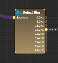
| Port | Direction | Type | Meaning |
|---|---|---|---|
| Spectrum | Input | Spectrum | Spectrum to read. |
| Bins, or Bins Ch0, Bins Ch1 and so on | Output | Channels | Use Multichannel on: one port per input channel, each holding one channel per bin. Each channel is named after its bin frequency. |
| One port per bin, named by frequency, such as 8.0Hz | Output | Channels | Use Multichannel off: each port holds that bin from every input channel. |
| Attribute | Values | Default | What it does |
|---|---|---|---|
| Use Multichannel | On, off | On | Bundles the selected bins into one multichannel output instead of one port per bin. |
| Lower Frequency | 0 to 200 Hz | 0 | Lower end of the selection. If it is above Upper Frequency, it is set to Upper Frequency. |
| Upper Frequency | 0 to 200 Hz | 128 | Upper end of the selection. A value above the spectrum’s top frequency selects the last bin. |
| Lock Ports | On, off | Off | Keeps the existing output ports when the node starts, instead of rebuilding them from the spectrum layout. |
Each bound selects the nearest bin. The node waits for the first spectrum to learn the layout, and it builds its output ports from that.
If input channels have different spectrum layouts, only the first channel is used, and the node shows no error.
In 1.7.3: Lower and Upper Frequency are cut to whole Hz when the node applies them, and each bound then selects the bin at or below it, not the nearest one.
Oscillator
Section titled “Oscillator”Generates a sine, square, triangle or sawtooth signal at a fixed sample rate.
| Port | Direction | Type | Meaning |
|---|---|---|---|
| Amplitude | Input | Channels | Optional. Overrides the Amplitude attribute. |
| Frequency | Input | Channels | Optional. Overrides the Frequency attribute, in Hz. |
| Phase | Input | Channels | Optional. Overrides the Phase attribute. |
| Out | Output | Channels | Generated signal, at Sample Rate. |
| Attribute | Values | Default | What it does |
|---|---|---|---|
| Sample Rate | Above 0 Hz | 128 | Output sample rate. Changing it resets the node. |
| Waveform | Sine, Square, Triangle, Sawtooth | Sine | Shape of the signal. |
| Amplitude | Any number | 1 | Peak-to-peak height. The output swings between -Amplitude/2 and +Amplitude/2. |
| Frequency | Above 0 Hz | 440 | Signal frequency. |
| Phase | -180 to 180 | 0 | Offset added to the waveform’s phase. |
Set Frequency or Sample Rate before use. The default 440 Hz is above half of the default 128 Hz sample rate, so the output aliases and is not a true 440 Hz signal.
Connect at least one input. In the code, the number of output channels follows the largest connected input, so with nothing connected the node creates no output channel. Unconnected inputs use their attribute values.
Connected inputs are read once per update, and the last sample is used. Until an input has a sample, the attribute value applies.
Phase is added to the waveform without any conversion, in radians, although the attribute range looks like degrees.
Custom Waveform
Section titled “Custom Waveform”Plays a waveform that you define as text, with value and duration pairs.
| Port | Direction | Type | Meaning |
|---|---|---|---|
| Activate | Input | Channels | Starts or gates playback, depending on Play Mode. |
| Out | Output | Channels | Generated signal. |
| Attribute | Values | Default | What it does |
|---|---|---|---|
| Sample Rate | Above 0 Hz | 128 | Output sample rate. |
| Waveform | Text, value1: |
Empty | The waveform. Durations are in seconds. A missing duration counts as 0. |
| Waveform Type | Steps, Linear | Steps | Steps holds each value. Linear interpolates between values. |
| Play Mode | Play Always and Forever; Play Once if sample received; Play Once if Input > 0.0; Play While Input > 0.0 | Play Always and Forever | When the waveform plays. See below. |
| Continuous Output | On, off | On | On: a constant sample rate stream, with 0.0 while nothing plays. Off: bursts of samples with no constant sample rate. |
| Play Mode | Behaviour |
|---|---|
| Play Always and Forever | Loops continuously. The value on Activate is ignored. |
| Play Once if sample received | Plays once when any sample arrives on Activate. Another sample after it ends starts it again. |
| Play Once if Input > 0.0 | Plays once when the last Activate sample is above 0. It can play again after the input has dropped to 0 or below. |
| Play While Input > 0.0 | Loops while the last Activate sample is above 0. |
If Waveform is empty, or its durations add up to 0, the node does not start and produces no output.
Connect Activate in every Play Mode. In the code, the number of output channels follows the connected input, so with nothing connected the node creates no output channel.
Note: In the code, playback reads a timing table that is never filled, so this node may output only 0, whatever Waveform contains. 1.7.3 has the same code. Check the output in a View node before you rely on it.
Bio Nodes
Section titled “Bio Nodes”This category contains the nodes for biofeedback and bio signal analysis.

Calculates a heart rate variability metric from RR intervals. It recalculates over a sliding window each time a new RR interval arrives.
| Port | Direction | Type | Meaning |
|---|---|---|---|
| RR | Input | Channels | RR intervals, one value per heartbeat. See the note on units below. |
| Output, named after the selected Method (RMSSD by default) | Output | Channels | The metric. One value per input value, with no fixed sample rate. |
| Attribute | Values | Default | What it does |
|---|---|---|---|
| Method | RMSSD, SDSD, EBC, RR50, pRR50, pRR20 | RMSSD | The metric to calculate. See the table below. |
| Number of RR Intervals | 2 or higher | 10 | How many RR intervals the sliding window holds. A window of N intervals has N-1 successive differences. |
| Method | Output |
|---|---|
| RMSSD | Root mean square of the successive differences. |
| SDSD | Standard deviation of the successive differences. |
| EBC | Estimated breath cycle: the largest minus the smallest RR interval in the window. |
| RR50 | Number of successive differences larger than 50 ms, in either direction. |
| pRR50 | RR50 divided by the number of differences. This is a fraction from 0 to 1, not a percentage. |
| pRR20 | Like pRR50, with a limit of 20 ms. |
In 1.7.3: RR50, pRR50 and pRR20 count a difference only when an interval is longer than the next one. 1.8.2 counts both directions, so these values can differ between versions.
Notes:
- Units: RR50, pRR50 and pRR20 compare differences with 0.05 and 0.02, so they expect RR intervals in seconds. The RR-Interval output of the Heartrate node is labelled ms and carries the raw sensor value, which standard Bluetooth LE heart rate sensors report in units of 1/1024 second. Scale it to seconds first, for example with a Remap node set to Input Min 0, Input Max 10240, Output Min 0, Output Max 10. RMSSD, SDSD and EBC use the unit of their input.
- Start of a session: until the window is full, RMSSD, SDSD, RR50, pRR50 and pRR20 count the missing values as 0, and EBC uses only the intervals received so far, so the first outputs are not meaningful.
- Chaining: the output has no fixed sample rate, so it can’t connect directly to a node that requires one, such as Threshold.
- Availability: the node has no platform limit. Heart rate input depends on the sensor and the driver, which is off by default. See Bluetooth Smart Heart Rate Sensors.
Threshold
Section titled “Threshold”
Compares its input with a threshold or a range. It reports how much of a recent interval passed the comparison, and whether the newest sample passes. Use it to turn a signal into a reward or inhibit value.
| Port | Direction | Type | Meaning |
|---|---|---|---|
| In | Input | Channels | The signal to compare. Required. |
| Thresh | Input | Channels | Overrides the Threshold attribute. Named Low when Use Range is on, where it overrides Low Threshold. |
| High | Input | Channels | Overrides High Threshold. Shown only when Use Range is on. |
| % Passed | Output | Channels | Samples that passed, divided by all samples in the interval. This is a fraction from 0 to 1. The interval slides by one sample, so there is one value per input sample. |
| Augment | Output | Channels | Based on the newest sample only. With a single threshold: 1 if it passes, otherwise 0. With a range: if it passes, its position in the range, mapped from Low to High onto 0 to 1; otherwise 0. |
| Inhibit | Output | Channels | 1 minus Augment. |
| Attribute | Values | Default | What it does |
|---|---|---|---|
| Interval Length | 0 to 30 seconds | 1 | The length of the interval behind % Passed. Do not use 0. See the notes. |
| Use Range | On, off | Off | Compares with a range instead of a single threshold. |
| Threshold (Low Threshold when Use Range is on) | Any number | 0.5 | The threshold, or the lower end of the range. Used while the matching port has no connection. |
| High Threshold | Any number | 0.8 | The upper end of the range. Used while the High port has no connection. Shown only when Use Range is on. |
| Compare Function (single threshold) | Equal to, Greater than, Less than, Grt. or Equal, Less or Equal, Inequal to | Greater than | How a sample x is compared with the threshold T. Shown only when Use Range is off. |
| Compare Function (range) | Within Range (exclusive), Within Range (inclusive), Outside Range (exclusive), Outside Range (inclusive) | Within Range (inclusive) | How a sample x is compared with the range from L to H. Shown only when Use Range is on. |
The range functions work as follows:
| Function | A sample passes when |
|---|---|
| Within Range (exclusive) | L < x < H |
| Within Range (inclusive) | L <= x <= H |
| Outside Range (exclusive) | x < L or x > H |
| Outside Range (inclusive) | x <= L or x >= H |
In 1.7.3: Choosing a range function doesn’t reliably apply it, because the code reads the single-threshold Compare Function instead. With the default Compare Function (Greater than), Outside Range acts as Within Range (inclusive). If that function is Less than or Grt. or Equal, Outside Range never passes for a valid range. With a single threshold, the attribute keeps the label Low Threshold.
Notes:
- Interval Length 0: Studio’s tooltip says 0 gives an infinite interval. The code doesn’t do that: with 0, the node produces no output.
- Start of a session: during the first Interval Length, the node compares zeros instead of the signal. With a function such as Less than, the outputs can show a pass before real data is evaluated.
- Outside Range and Augment: the mapping onto 0 to 1 is not clamped. A sample that passes outside the range gives an Augment value below 0 or above 1, and Inhibit moves with it.
- Turning Use Range off: this removes any connection to the High port.
- Multiple channels: each input channel gets its own comparison. A threshold port must have one channel, or the same number of channels as In.
Errors:
| Message | Cause |
|---|---|
| Input must have a valid sample rate. | An input has no fixed sample rate, for example the output of an HRV node. |
| Input channel is not synchronized to engine. | An input is not synchronized to the Engine. |
| Sizes of input multichannels are incompatible. | The channel counts of the ports don’t match. |
Auto Threshold
Section titled “Auto Threshold”Adapts a threshold to the recent signal, so that feedback stays at a target level as the signal changes. You set one threshold and a target. The node learns the signal’s distribution over a sliding window and calculates the other threshold.
| Port | Direction | Type | Meaning |
|---|---|---|---|
| Signal | Input | Channels | The signal to learn from. Required. |
| Target | Input | Channels | The target as a value from 0 to 1. Required. See the Target attribute. |
| High | Input | Channels | The fixed high threshold. Connecting it makes the node calculate the low threshold. |
| Low | Input | Channels | The fixed low threshold. Connecting it makes the node calculate the high threshold. |
| High | Output | Channels | The high threshold, fixed or calculated. |
| Low | Output | Channels | The low threshold, fixed or calculated. |
Connect exactly one of the High and Low inputs. The outputs run at the sample rate of the Target port, not of the Signal port. You can feed Target and the fixed threshold from Parameter nodes, and connect the outputs to the Low and High ports of a Threshold node.
| Attribute | Values | Default | What it does |
|---|---|---|---|
| Number of Bins | 100 or higher | 10000 | The resolution of the histogram that holds the signal’s distribution. More bins give finer threshold steps. |
| Sample Count | 2 or higher | 128 | The window size, in samples of the Signal port. The window in seconds is Sample Count divided by the signal’s sample rate, so the default is 1 second at 128 Hz. |
| Target | Average Score, Trigger Ratio | Average Score | How the Target port is interpreted. See below. |
| Invert Target | On, off | Off | Uses 1 minus the Target input. |
| Threshold Input | Absolute, Relative | Relative | How the fixed threshold input is interpreted. See below. |
Studio shows no tooltips for these attributes.
Target modes. The node moves the calculated threshold away from the fixed one, and stops at the first position that reaches the target.
| Mode | The target is reached when |
|---|---|
| Average Score | The average distance of the samples from the calculated threshold, as a fraction of the gap between the two thresholds, reaches Target. Samples outside the two thresholds count as 0. |
| Trigger Ratio | The share of samples in the window that lie between the two thresholds reaches Target. |
If the target can’t be reached, the calculated threshold stops at the edge of the histogram.
Threshold Input modes.
| Mode | Fixed threshold |
|---|---|
| Absolute | The input value itself. |
| Relative | E + E x input, where E is the highest sample value in the window for the High input, or the lowest for the Low input. An input of 0 uses E itself. An input of 0.1 moves the threshold by 10% of E, so the direction depends on the sign of E. |
Notes:
- Start of a session: the calculated threshold is 0 until Sample Count samples have arrived. In Relative mode, the fixed threshold is 0 as well.
- Changing an attribute: this restarts the node, and the learned distribution is lost.
- Session pause: while a session is paused, the histogram is held, so the thresholds stop adapting. The node keeps producing output. After the pause, it rebuilds the histogram from one full window.
- Multiple channels: each Signal channel gets its own histogram and outputs. Target and the threshold input must have one channel, or the same number of channels as Signal. Otherwise the node doesn’t run.
In 1.7.3: The thresholds keep adapting during a session pause. The histogram is also rebuilt from the newest window on nearly every update, rather than updated sample by sample.
Errors:
| Message | Cause |
|---|---|
| Sizes of input multichannels are incompatible. | Two connected ports both have more than one channel, and the counts differ. |
| Missing threshold input | Neither High nor Low is connected, or Signal has one channel and the connected threshold port has several. |
| More than one threshold defined | Both High and Low are connected. |
| Samplerates of control ports don’t match | The sample rate of Target differs from that of the connected threshold port. |
The node also doesn’t run without valid Signal and Target inputs, and shows no specific message for that.
Utils Nodes
Section titled “Utils Nodes”This category contains utility nodes and nodes for channel management. The View node sits in the Output category.
Unless a section says otherwise, a node handles each channel of its input separately.
Smoothing
Section titled “Smoothing”
Removes noise and steps from a signal by moving its output gradually towards each new input value. Don’t use it as a lowpass filter. Use the IIR/FIR Filter node for that.
| Port | Direction | Type | Meaning |
|---|---|---|---|
| In | Input | Channels | Signal to smooth. |
| Out | Output | Channels | Smoothed signal, same sample rate. |
| Attribute | Values | Default | What it does |
|---|---|---|---|
| Interpolation Speed | 0 to 1 | 0.75 | How quickly the output follows the input. 0 holds the output at its current value. 1 passes the input through unchanged. |
| Start Value | Any number | 0 | Output value that interpolation starts from. |
The speed is divided by the sample rate for each sample. At 128 Hz and 0.75, each output sample moves about 0.6% of the way to the input, so the output takes roughly 1 / speed seconds to catch up. The speed therefore behaves as a rate per second, and values just below 1 smooth far more than 1 does.
The input needs a fixed sample rate. With a variable rate input, the node logs “Invalid sample rate” and produces no output.
In 1.7.3: The node has no check for a variable rate input.
Delays a signal by a time or a number of samples. The node outputs 0 until the delay is reached.
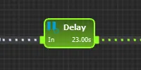
| Port | Direction | Type | Meaning |
|---|---|---|---|
| In | Input | Channels | Signal to delay. |
| Out | Output | Channels | Delayed signal. The port label shows the delay, for example 23.00s or 100 smpl. |
| Attribute | Values | Default | What it does |
|---|---|---|---|
| Set by Time | On, off | On | On: the delay is set in seconds, so it stays the same if the sample rate changes. Off: the delay is set in samples. |
| Delay (Seconds) | 0 or higher | 0 | Delay time. Shown only when Set by Time is on. |
| Delay (Samples) | 0 or higher | 0 | Number of samples. Shown only when Set by Time is off. |
With Set by Time on, the input needs a fixed sample rate, or the node shows the error “Input must have a valid sample rate.” The delay is rounded to the nearest whole sample, and Delay (Seconds) is updated to the rounded value.
Resample
Section titled “Resample”
Changes the sample rate of a signal.
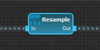
| Port | Direction | Type | Meaning |
|---|---|---|---|
| In | Input | Channels | Signal to resample. |
| Out | Output | Channels | Signal at the target sample rate. |
| Attribute | Values | Default | What it does |
|---|---|---|---|
| Sample Rate | Above 0 Hz | 128 | Target sample rate. |
| Mode | Realtime | Realtime | Read only. The field cannot be changed, so the node always uses Realtime. |
What the node does depends on the input:
- Input already at the target rate: samples are forwarded unchanged.
- Input with a fixed rate: each output sample takes the most recent input sample at that time. No lowpass filtering is applied, so filter the signal first if you downsample.
- Input with a variable rate: the node repeats the latest input value at the target rate.
Freeze
Section titled “Freeze”
Holds a signal at one value after a set time or number of samples.
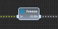
| Port | Direction | Type | Meaning |
|---|---|---|---|
| In | Input | Channels | Signal to freeze. |
| Out | Output | Channels | Input before the freeze, then the frozen value. The port label shows the delay, for example 15.00s or 100 smpl. |
| Attribute | Values | Default | What it does |
|---|---|---|---|
| Delay Type | Duration, Sample Count | Duration | How the delay is set. |
| Delay (Seconds) | 0 or higher | 1 | Freeze after this much data. Shown only for Duration. |
| Delay (Samples) | 0 or higher | 100 | Freeze after this many samples. Shown only for Sample Count. |
| Pass Through | On, off | On | On: forward the input until the freeze. Off: output 0 until the freeze. With a variable rate input, output nothing until the freeze. |
The frozen value is the input sample at the moment the delay is reached. After that, the node outputs the frozen value for every input sample until the node is reset.
With Delay Type set to Duration, the input needs a fixed sample rate, or the node shows the error “Input must have a valid sample rate.” The delay is rounded to the nearest whole sample.
Merge Channels
Section titled “Merge Channels”
Combines several single channels or multichannels into one multichannel.
| Port | Direction | Type | Meaning |
|---|---|---|---|
| In (one or more) | Input | Channels | Signals to merge. The node always keeps one free In port and adds another when you connect the last one. |
| Out | Output | Channels | All input channels in one multichannel, with their names, ranges and colors kept. |
This node has no attributes you can set.
All inputs must have the same sample rate, or the node shows the error “Input sample rates are incompatible.”
Select Channels
Section titled “Select Channels”
Picks channels out of a multichannel, by name or by position, and gives you access to them separately or as a smaller multichannel.
| Port | Direction | Type | Meaning |
|---|---|---|---|
| In | Input | Channels | Multichannel to select from. |
| One port per selected channel | Output | Channels | The selected channel. Each port is labelled with its channel name. Ports are labelled - until the node has started. |
| Out | Output | Channels | With Single Output on, replaces the ports above and carries all selected channels. |
| Attribute | Values | Default | What it does |
|---|---|---|---|
| Channels | Comma-separated list | * |
Channels to use, see below. An empty list selects nothing. |
| Single Output | On, off | Off | Puts all selected channels into one multichannel on one port. |
| Quick Config | On, off | Off | Lets users choose the channels outside the graph, see below. |
Each entry in Channels can be one of these:
*as the first entry: all input channels.- A channel name, such as
Fp1: the first channel with exactly that name. - A number, such as
2: the channel at that position, counting from 1. *text*: every channel whose name containstext.
If a name or number matches nothing, the node shows the error “Channel ‘name’ not found” and that output carries 0. Wildcard entries that match nothing cause no error.
With Quick Config on, the node can be configured in the Experience Wizard. To open the wizard, click Select User, select a user in the list, then click Create Protocol. These controls are not available on every account. The Session Control window also shows up to four Channels dropdowns that list the input channels. Your choice is applied to the first Select Channels node in the classifier with Quick Config on. The 2D Spectrogram window ticks the channels this node selects.
In 1.7.3: The 2D Spectrogram window doesn’t follow this selection. Also, if no channel is selected when the node starts, it removes its output ports and their connections.
Transpose Channels
Section titled “Transpose Channels”Swaps the two dimensions of a set of multichannels. For example, connect one multichannel per frequency band, each with channels Fp1 and Fp2. The output is one multichannel per electrode, each holding all bands.
| Port | Direction | Type | Meaning |
|---|---|---|---|
| In (one or more) | Input | Channels | Multichannels to transpose. The node always keeps one free In port and adds another when you connect the last one. |
| One port per input channel position | Output | Channels | The channel at that position from every connected input. Each port is labelled with the channel name from the first input. |
This node has no attributes you can set.
Each output channel is named after its source node and channel, for example Alpha Fp1.
All connected inputs must have the same number of channels, or the node shows the error “All inputs must have equal number of channels.” They must also have the same sample rate, or it shows “Input sample rates are incompatible.”
Rename
Section titled “Rename”
Renames channels, or adds text before or after their names.
| Port | Direction | Type | Meaning |
|---|---|---|---|
| In | Input | Channels | Signal to rename. |
| Out | Output | Channels | Same samples, with new channel names. |
| Attribute | Values | Default | What it does |
|---|---|---|---|
| Channel Names | Text, comma-separated for a list | Empty | New names, or the text to add. Empty keeps the input names. |
| Mode | Rename, Prefix, Postfix | Rename | Rename replaces the name. Prefix adds the text before it. Postfix adds the text after it. |
One entry applies to every channel, so in Rename mode all channels get the same name. A list applies by position, and channels beyond the end of the list keep their input names. In Rename mode, an empty list entry keeps that channel’s input name, and spaces around names are removed. In Prefix and Postfix modes, spaces are kept, so you can add them on purpose. An entry made only of spaces applies only to the first channel, so include visible text if every channel needs it, or give one entry per channel.
Recolor
Section titled “Recolor”Sets the display color of each channel.
| Port | Direction | Type | Meaning |
|---|---|---|---|
| In | Input | Channels | Signal to recolor. |
| Out | Output | Channels | Same samples, with new channel colors. |
| Attribute | Values | Default | What it does |
|---|---|---|---|
| Channel Colors | Comma separated list of #RRGGBB values |
Empty | Colors applied by position. An invalid entry keeps that channel’s input color. |
| Add Color | Color | neuromore blue (#009FE3) |
Picking a new color adds it to Channel Colors. Channels beyond the end of the list use this color. |
With the defaults, every channel is shown in neuromore blue.
Channel Info
Section titled “Channel Info”Outputs a property of the input channel instead of its values, with one output sample for each input sample.
| Port | Direction | Type | Meaning |
|---|---|---|---|
| In | Input | Channels | Channel to inspect. |
| Output, labelled with the Info Type | Output | Channels | The selected property, at the input’s sample rate. |
| Attribute | Values | Default | What it does |
|---|---|---|---|
| Info Type | See below | Sample Rate | Property to output. |
| Info Type | Output |
|---|---|
| Sample Time | Time of this sample, in seconds. |
| Sample Index | Index of this sample. |
| Sample Rate | Sample rate in Hz. |
| Available Samples | Number of samples the channel holds. |
| New Samples | Number of new samples on the channel. |
| Buffer Size | Maximum number of samples the channel holds. |
| Elapsed Time | Elapsed time of the channel, in seconds. |
| Last Sample Time | Time of the last sample, in seconds. |
| Start Time | Start time of the channel, in seconds. |
| Is Independent? | 1 if the channel is independent, otherwise 0. |
Meta Info
Section titled “Meta Info”Outputs a value about a channel, the classifier or the Engine at its own sample rate. Use it to monitor a running classifier.
| Port | Direction | Type | Meaning |
|---|---|---|---|
| In | Input | Channels | Channel to inspect. Optional. Only needed for the channel and multichannel info types. Channel info types read the first channel. |
| Output, labelled with a short form of the Info Type | Output | Channels | The selected value. |
| Attribute | Values | Default | What it does |
|---|---|---|---|
| Info Type | See below | Channel: Sample Rate | Value to output. |
| Sample Rate | 0 Hz or higher | 128 | Sample rate of the output. At 0, the node outputs a sample only when the value changes. |
| Info Type | Output |
|---|---|
| Number of Channels in Multichannel | Channels on the input. |
| Channel: Sample Rate | Sample rate in Hz. |
| Channel: Sample Counter | Number of samples so far. |
| Channel: Number of Samples | Number of samples the channel holds. |
| Channel: Number of added samples | Number of new samples on the channel. |
| Channel: Buffer Size (bytes) | Maximum number of samples the channel holds. The value is a sample count, despite the label. |
| Channel: Elapsed Time (seconds) | Elapsed time of the channel. |
| Channel: Last Sample Time (seconds) | Time of the last sample. |
| Channel: Start Time (seconds) | Start time of the channel. |
| Channel: Is Independent? | 1 if the channel is independent, otherwise 0. |
| Channel: Latency (seconds) | Latency of the channel. |
| Classifier Buffer Usage (bytes) | Memory used by the classifier’s channel buffers. |
| Classifier Maximum Output Latency (seconds) | Highest latency across the classifier’s output nodes. |
| Engine Update Loop Performance (ms) | Worst-case time of the Engine update loop. |
| Engine Classifier Performance (ms) | Worst-case time of the active classifier. |
With no input connected, channel info types output 0.
Sample Gate
Section titled “Sample Gate”Lets samples through or discards them, based on a control signal. Discarded samples are lost, not delayed.
| Port | Direction | Type | Meaning |
|---|---|---|---|
| In | Input | Channels | Signal to gate. Must be connected. |
| Control | Input | Channels | Gate control. The gate is open when the value is 1 or more, and closed otherwise. Use one channel for all input channels, or one per input channel. |
| Out | Output | Channels | The samples that passed the gate, at a variable sample rate. |
| Attribute | Values | Default | What it does |
|---|---|---|---|
| Default State | Closed, Open | Closed | Gate state when Control is not connected, or when a single Control channel at a different rate has no new data. |
If Control and In have the same fixed sample rate, each input sample is gated by its matching control sample. Otherwise, the node reads the newest control value at each Engine update. If no new control sample arrived in that update, it uses Default State. The exception is two or more Control channels, one per input channel, at a different or variable rate. There, the gate counts as closed when no new control sample arrives, whatever Default State says, and an open gate passes at most one sample per channel per Engine update.
The wrong number of control channels gives the error “Control port has wrong number of channels.”
The output has a variable sample rate, so nodes that need a fixed rate after it show the error “Input must have a valid sample rate.” Add a Resample node between them if you need a fixed rate.
A text box for comments in the graph. It has no ports and does not affect the signal.
| Attribute | Values | Default | What it does |
|---|---|---|---|
| Text | Text | Put some; |
The text to show. A semicolon starts a new line. |
| Horizontal Alignment | Left, Center, Right | Center | Horizontal position of the text. |
| Vertical Alignment | Top, Center, Bottom | Center | Vertical position of the text. |
| Node Width | 10 to 32767 | 150 | Width in pixels at 96 dpi. |
| Node Height | 10 to 32767 | 100 | Height in pixels at 96 dpi. |
| Node Color | Color | Grey | Color of the note. |
Color Wheel
Section titled “Color Wheel”Converts hue, saturation and value signals to red, green and blue signals. The node itself takes on the output color of its first channel.
| Port | Direction | Type | Meaning |
|---|---|---|---|
| Hue | Input | Channels | Hue from 0 to 1, around the color wheel. Must be connected, or the node does not run. |
| Saturation | Input | Channels | Saturation from 0 to 1. If not connected, the node uses 1. |
| Value | Input | Channels | Brightness from 0 to 1. If not connected, the node uses 1. |
| R | Output | Channels | Red, 0 to 1. |
| G | Output | Channels | Green, 0 to 1. |
| B | Output | Channels | Blue, 0 to 1. |
This node has no attributes.
Input values outside the range are clamped. All inputs must have the same sample rate, or the node shows the error “Input sample rates are incompatible.”
Switch
Section titled “Switch”Forwards one of several inputs to its output, chosen sample by sample by a control signal.
| Port | Direction | Type | Meaning |
|---|---|---|---|
| Control | Input | Channels | Selects the input. Use one channel for all signal channels, or one per signal channel. |
0 .. 1, 1 .. 2, and so on |
Input | Channels | Signals to choose from. The label is the control range that selects the port. |
| Out | Output | Channels | The selected signal. |
| Attribute | Values | Default | What it does |
|---|---|---|---|
| Inputs | 2 or higher | 2 | Number of signal input ports. |
The control value is cut down to a whole number, so 1.7 selects the port labelled 1 .. 2. Values at or above the number of inputs select the last port. Keep the control at 0 or above, because negative values are not handled explicitly.
All ports must be connected before the node runs. Errors:
- “Input sample rates are incompatible.” All inputs, including Control, must have the same sample rate.
- “Control channel is incompatible.” Control must have one channel, or as many channels as each signal input.
- “Input channels are not compatible.” All signal inputs must have the same number of channels.